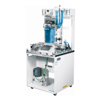
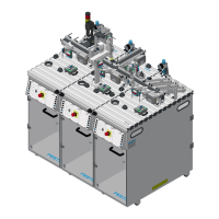
The Festo Didactic Pick&Place station is a learning system designed for vocational and further training in automation and technology. It utilizes didactically prepared industrial components to facilitate practical, project-oriented learning.
Function Description
The Pick&Place station is an automated insertion device. According to DIN 8593-1, insertion is defined as the process of inserting an assembly component into a shaped element of another assembly component. This station specifically realizes the insertion of a workpiece insert into a workpiece housing. Available workpiece inserts include a clock, a thermometer, and a hygrometer.
The station's primary functions are:
- Transporting workpiece housings.
- Stopping workpiece housings.
- Inserting workpiece inserts.
- Separating complete workpieces (housing and insert).
It can also be configured for:
- Segregation of workpieces (housings or bodies) onto the slide.
- Alternative feeding of workpieces (housings or bodies) from the slide.
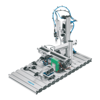
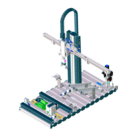
The Pick&Place station is equipped with a two-axis Pick&Place module. Workpiece housings placed on the conveyor belt are detected by a diffuse sensor. The workpiece is then transported to a pneumatic separator on the conveyor belt and detected by a second diffuse sensor. The Pick&Place module picks up a workpiece insert from the slide and places it onto the workpiece housing. The complete workpiece (housing and insert) is released by the separator and transported to the end of the conveyor belt, where a light barrier detects it.
Sequence Description:
- If a workpiece is detected, the conveyor belt motor switches on, and the workpiece is transported to the separator.
- The conveyor belt motor switches off when the workpiece is detected by the diffuse sensor in front of the separator.
- A workpiece insert is picked up from the slide and inserted into the housing.
- The separator reverses, and the conveyor belt motor switches on.
- The complete workpiece is detected at the end of the conveyor belt, and the conveyor belt motor switches off.
Initial Position:
- Separator extended.
- Belt drive switched off.
- Mini slide up.
- Mini slide retracted.
- Vacuum off.
Start Prerequisites:
- No workpiece at the start of the conveyor belt.
- Slide filled with workpiece inserts.
Important Technical Specifications
The Pick&Place station comprises several modules:
- Pick&Place module
- Conveyor belt module
- Slide module
- Profile plate
- Trolley
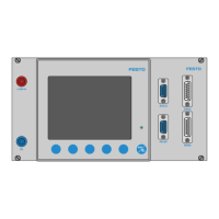
- Control console
- PLC board
Key Technical Data:
- Operating pressure: 6 bar (600 kPa)
- Voltage supply: 24 V DC, 4.5 A
- Digital inputs: 8
- Digital outputs: 6
Pick&Place Module: This is a pneumatic handling device built from precise slide units. End positions of the slides are sensed electrically via proximity sensors. A bellows suction cup picks up workpiece inserts, with a vacuum filter directly mounted to prevent dirt particles from reaching the vacuum generator.
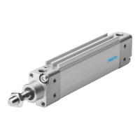
Conveyor Belt Module: Used for transporting and buffering workpieces. Workpieces at the start, before the separator, and at the end of the conveyor belt are detected by optical sensors with fibre-optic cables. The belt is driven by a DC gear motor. A solenoid-actuated separator stops and separates outgoing workpieces, with end position sensing by inductive sensors.
Slide Module: Transports or stores workpieces. Its inclination and height are variably adjustable, accommodating up to 6 workpiece inserts.
Usage Features
The station is delivered fully assembled, functionally adjusted as a single station, commissioned, and tested. For combinations of stations, mechanical adjustments and sensor positioning/settings may be necessary.
Commissioning involves:
- Workstation setup: Requires the assembled and adjusted station, a control console, a PLC board, a 24 V DC 4.5 A power supply unit, a compressed air supply of 6 bar (600 kPa) with approx. 50 l/min suction capacity, and a PC with PLC programming software.
- Mechanical setup: Instructions for assembling the profile plate, control console, and the station itself are provided in the accompanying CD-ROM.
- Sensor adjustment:
- Proximity sensor (Pick&Place, mini slides): Used for end position sensing, sensitive to a permanent magnet. Adjustment involves moving the sensor until the LED switches on, then slightly further until it switches off, and finally positioning it halfway between these points.
- Pressure switch (Pick&Place, vacuum suction cup): Detects partial vacuum at the suction cup. When a workpiece is securely picked up, it provides an output signal. Adjustment involves picking up a workpiece, pressing the EDIT button until the LED flashes, and releasing it to store the current pressure as the switching pressure.
- Diffuse sensor (Conveyor belt, detection of workpieces): Detects workpieces by reflected red light. Adjustment involves placing a black workpiece at the start of the belt and adjusting the potentiometer until the LED switches on. All workpieces should be securely detected.
- Through-beam sensor (Conveyor belt, detection of workpieces): Monitors the filling level of the stack magazine. The workpiece interrupts the light barrier. Adjustment involves aligning transmitter and receiver fibre optic cables and adjusting the potentiometer until the LED switches on. The LED should switch off when a workpiece is in the sensing range.
- Adjusting one-way flow control valves: Used to regulate exhaust air flow rates for double-acting cylinders. Initially, screw in the restrictors completely, then loosen one turn. During a test run, slowly open the valves until the desired speed is reached.
- Visual check: Before each start-up, check electrical connections, compressed air connections, and mechanical components for defects.
- Cable connections: Detailed instructions are provided for connecting the PLC board to the station's I/O terminal, the control console, the power supply unit, and the PC to the PLC.
- Pneumatic connection: Connect the compressed air supply to the start-up valve with filter-control valve, set to 6 bar (600 kPa).
- Manual override (HHB): Used to check valve functionality. Press the stem of the manual override to actuate the valve.
- Voltage supply: The station is supplied with 24 V DC (max. 5 A) via a power supply unit, with the PLC board managing the overall voltage supply.
- Loading the PLC program: Detailed steps are provided for Siemens, Festo, Allen Bradley, and Mitsubishi/MELSEC controllers, including connecting the PC to the PLC, resetting PLC memory, and downloading the project file.
- Starting the sequence: Fill the slide with workpiece inserts, check power and air supply, remove workpieces from transfer points, perform a reset sequence, place a workpiece on the conveyor belt, and start the sequence using the illuminated START button. The sequence can be interrupted by EMERGENCY-STOP or STOP buttons. AUTO/MAN key-operated switch allows selecting continuous or individual cycles. For multiple stations, resetting occurs against the material flow.
- Combination of stations (Networking): MPS stations are linked using optical sensors (StationLink). Transmitters on the incoming side and receivers on the outgoing side signal readiness or busyness. Sensors must be aligned, and stations securely interconnected.
- Hardware modifications: If the Pick&Place station is combined with a downstream station, the mechanical stopper at the end of the conveyor belt must be removed.
Maintenance Features
The Pick&Place station is largely maintenance-free. Regular cleaning is recommended for:
- Lenses of optical sensors, fibre-optics, and reflectors.
- Active surface of the proximity sensor.
- Entire station.
Use a soft, fluff-free cloth or brush for cleaning. Aggressive or abrasive cleaning agents must not be used.