2
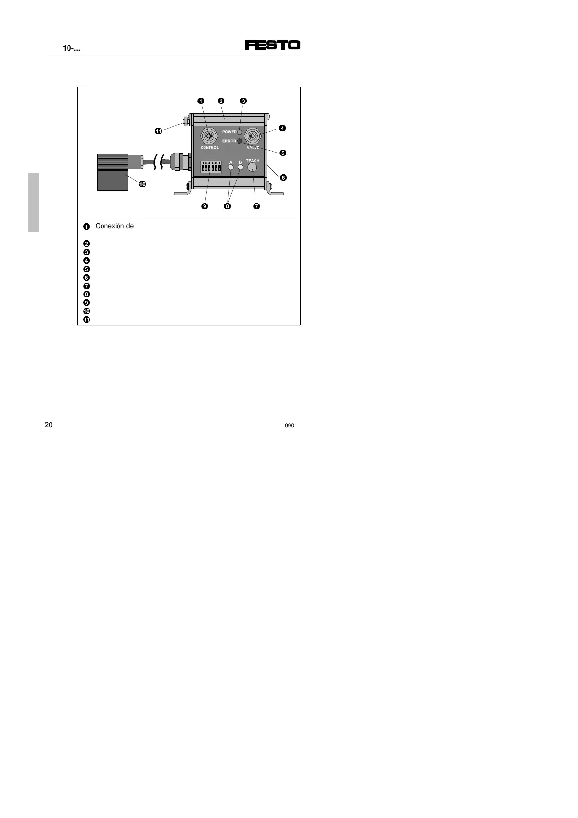
Elementos de conexión e indicación
1
2
3
4
5
6
7
8
9
0
!
Conexión de la tensión de funcionamiento, entradas y salidas
(CONTROL)
Ranura para las placas de identificación (tipo ISB 6x10)
LED verde, indicación de la tensión de funcionamiento (POWER)
Conexión de la válvula (VALVE)
LED rojo, indicación de error (ERROR)
Placa de tipo (ver superficie lateral)
Tecla TEACH, determinación de las posiciones finales (topes fijos)
LEDs amarillos para indicación de posición (A, B)
Interruptor DIL (microinterruptor) para configuración
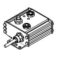
Conexión al potenciómetro con clavija
Conexión a Tierra/Masa
1
2
!
4
5
6
7
8
9
0
3
Español
SPC-10-...
20
9902c
 Loading...