INSTALLATION
15.
RADIO CONNECTIONS
To ensure proper operation, the connection to the radio should be performed by a
Qualified Radio Technician.
23. If you are using a radio-specific interface cable, follow the directions included with
the interface cable, then proceed with step 27 in this Installation Procedure.
If you are unsure if your Interface Cable is the proper one, or if you want to know
if Firecom manufactures a Radio-Specific Interface Cable for your radio(s),
contact your local Firecom Dealer.
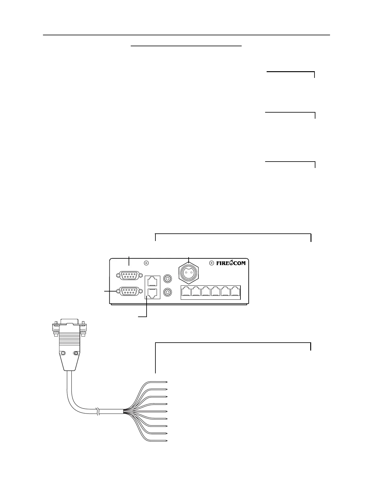
24. Plug the 9-Pin plug on the end of the MR-0X Mobile Radio Interface Cable into
the desired Radio Interface Jack on the rear of the intercom (Figure 16).
Tighten the 2 screws on the plug of the MR-0X. If these screws are not tightened,
the 9-pin plug may vibrate loose and cause problems with transmission, recep-
tion or other radio problems.
25. Using the information in Figure 17, connect the wires on the MR-0X Mobile
Radio Interface Cable to the appropriate places on the 2-way radio.
26. If the intercom is a 3020R repeat steps 23 to 25 for the second radio.
FIGURE 16:
3020R Rear Panel
FIGURE 17:
MR-OX Universal Radio
Interface Cable
9-Pin Plug:
to Intercom Radio
Interface Port
Pin #1: Brown - TX Audio Hi
Pin #2: Red - TX Audio Lo
Pin #3: Orange - PTT Hi
Pin #4: Yellow - PTT Reference
Pin #5: Green - Hook Switch Relay (N.O.)
Pin #6: Blue - RX Audio Hi
Pin #7: Violet - RX Audio Lo
Pin #8: Gray - Hook Switch Relay (N.C.)
Pin #9: Black - Hook Switch Relay (C.)
IMPORTANT
IMPORTANT
IMPORTANT
Radio B
Interface Jack
Power
Connector
Radio A
Interface
Jack
Remote Jacks
(Identical)
POWER
INTERCOM
AUX
RADIO B
RADIO A
REMOTE
IN
OUT
PR