6
BURNER TECHNICAL SPECIFICATION
14
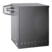
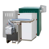
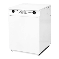
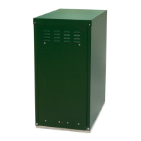
FIREBIRD ‘S’ RANGE
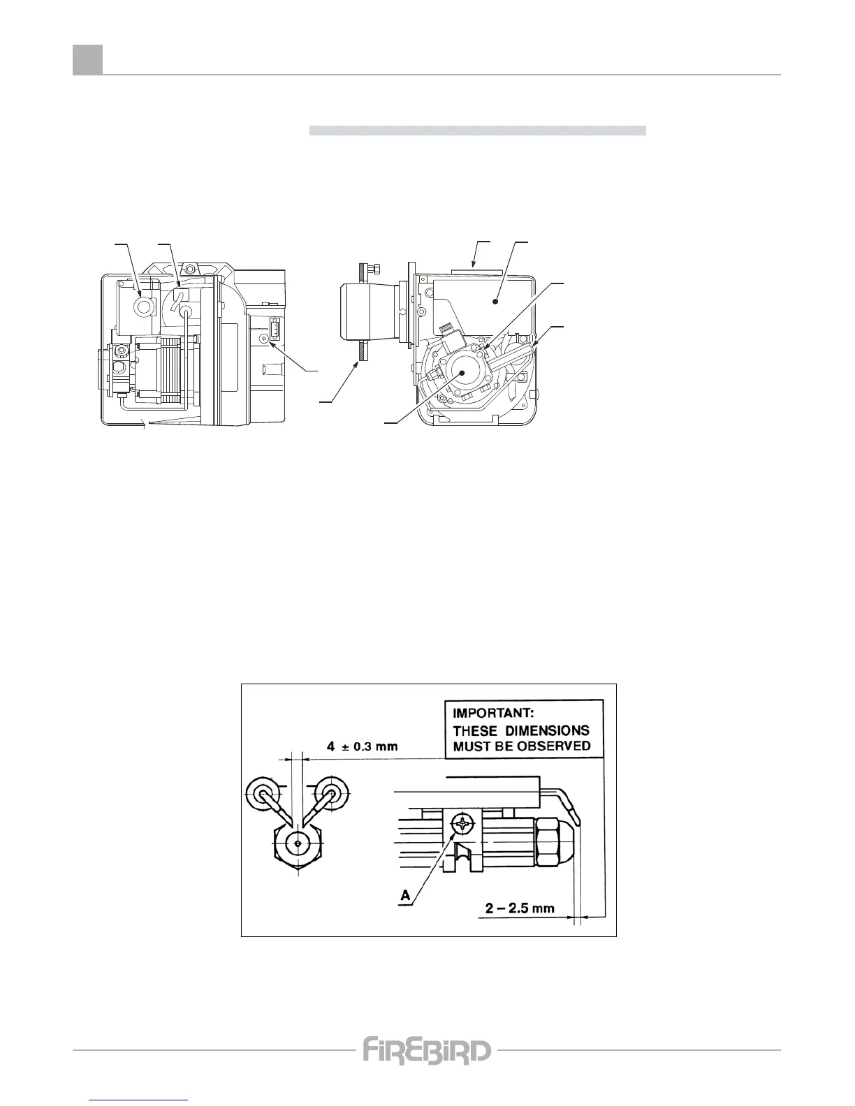
ELECTRODE SETTING
Riello RDB 2.2
ATTENTION
Before assembling or removing the nozzle loosen screw (A) and move electrodes forward.
1. BURNER DESCRIPTION
One stage kerosene burner.
1.1 BURNER EQUIPMENT
Flange with insulating gasket . . . . . . . No. 1 Screws for flange to be fixed to boiler . . . . . . No. 4
Screw and nuts for flange . . . . . . . . . No. 1 Flexible oil pipes with nipples. . . . . . . . . . . . . No. 2
Hexagonal key . . . . . . . . . . . . . . . . . . No. 1 Screw of by-pass pump . . . . . . . . . . . . . . . . . No. 1
Plastic air cover . . . . . . . . . . . . . . . . . No. 1
The intake air temperature must not be over 70˚.
Burner with CE marking in conformity with EEC directives: EMC 89/336/EEC and Efficiency 92/42/EEC.
CE Certification No.: 0036 0316/01 as 92/42/EEC.
1 - Pump
2 - Control box
3 - Reset button with lock-out lamp
4 - Flange with insulating gasket
5 - Air damper adjustment screw
6 - Snorkel (BF)
7 - Pump pressure adjustment screw
8 - Pressure gauge port
9 - Photoresistance
1
D4138
Fig. 1
4
6
5
2
3
7
8
9
 Loading...