7
19 20 21 22 23 2416 17 1813 14 15
121110
1
2
C
12
Pressure
L2
14
L1
N
EL
L
N
L2
N
(L2)
E
Mains Plug.
E
C
1
2
1 2 C
E
2 E C
Safety Limit
Thermostat.
Control
Thermostat.
Insert Link A.
14
18 13
15 E NL
Burner Lockout.
To Burner
Mains In Here.
Safety Limit Thermostat.
Temperature
Control Dial
Reset Pin Inside
Screw Off Cover
To Dual Temperature Control Thermostat
And Safety High Limit Thermostat
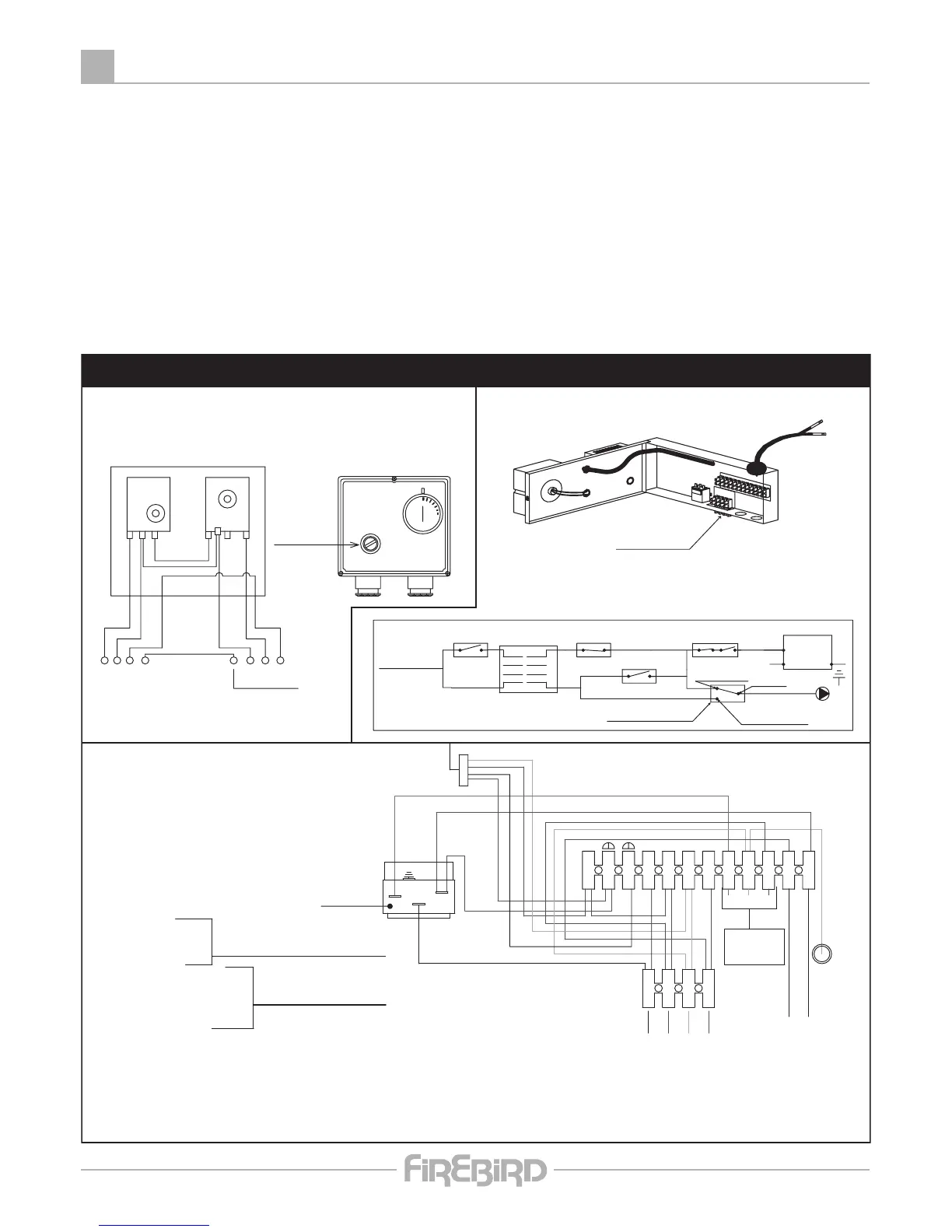
Firebird Kitchen C, System C & Heat Pac C' Wiring Diagram
Fitted only on
Kitchen C Boilers
1.Lamp Neutral.
2.Mains On Lamp.
3.Lock out Lamp.
4.Permanent Live Frost Stat.
5.Neutral For Frost Stat.
6.Earth For Frost Stat.
7.-Live From Frost Stat.
8.-Power Supply For Pump From Common On Over Heat.
23. - To Pressure Switch.
25.- To Dual Stat. And Burner.
12.- Switch Live To Poll 1 On Over Heat Stat.
L2.- Permanent Live To Poll 2 On Over Heat Stat.
24.-Return From Pressure Switch.
Fitted On Heat Pac's
to GB Only
L2.- Permanent Live.
L.- Switched Live.
N.- Neutral.
E - Earth.
Pump
Overheat
Thermostat
Circulating
Pump
E.
N.
L.
L2.
N.
TIME-SWITCH
4 Pin Isolating Plug
Over Heat Thermostat Set at 93˚C
Normally Open
Contacts Close
On Rising Temp.
PUMP
FROST THERMOSTAT
PRESSURE SWITCH
MAINS IN
Protect Supply With
5 Amp
CONTROL STAT. & LIMIT STAT.
HEATING
UNIT
Normally Closed
Contacts Open
On Rising Temp.
Common
Pressure Switch
Circuit closes on drop of
system pressure. (.2bar)
Mains Plug.
PUMP OVER HEAT THERMOSTAT
NOT IN KITCHEN MODELS
17 18 20 2114 1513 16 24232219
56 892314 1211107
ELECTRICAL SUPPLY
The boiler and controls require 230V 1 phase 50Hz electric supply protected with a 5amp fuse.
THIS APPLIANCE MUST BE EARTHED.
A qualified electrician must carry out all electric wiring in accordance with current I.E.E Regulations and any local
regulations which may apply.
The mains electrical supply must be taken from a double pole isolating switch with a 5amp fuse, positioned somewhere
close to the boiler. Heat resisting cable must be used which can be routed into the boiler through the access provided
on either side of the base.
Ancillary controls may be provided for with terminal connections in the control panel.
 Loading...