EQUIPMENT: FIRECLASS Prescient III WRITTEN BY: RKP
PUBLICATION: OMFCPRES3IN CHECKED BY: AP
ISSUE No. & DATE: 0 02/02/12
PAGE 18 of 43
indicate that the Extinguishing System Reset is
inhibited.
3.19.5. SILENCE BUZZER
This button silences the internal buzzer during any
fault or alarm condition. The accompanying yellow
LED is illuminated steady to indicate that the
buzzer has been silenced. Any new fault or alarm
will restart the buzzer and clear the LED.
3.19.6. AUTO & MANUAL / MANUAL ONLY
This button toggles the panel status between
(Automatic & Manual) and (Manual Only) modes.
If any Field Auto/Manual switch is in the Manual
Only position, then this button has no effect (the
Manual Only LED will be flashing).
3.19.7. SELECT ON/OFF
This button toggles the Circuit Select Cursor On
and OFF. See section 4.2 for more details.
3.19.8. ENABLE
This button has no function unless the Circuit
Select Cursor is ON. Depending on the current
mode, operation of the button can re-enable a
previously disabled circuit, set a zone for
intrinsically safe operation or move the cursor
between SLU number and SLU type code digits.
See section 4.2 for details.
3.19.9. DISABLE
This button has no function unless the Circuit
Select Cursor is ON. Depending on the current
mode, operation of the button can disable a circuit
or clear a zone from intrinsically safe operation.
See section 4.2 for details.
3.19.10. TEST
When the Circuit Select Cursor is OFF this button
operates the Test Display feature, sounding the
internal buzzer and illuminating all the LEDs on
the Display and internal control board for five
seconds. When the Circuit Select Cursor is ON,
depending on the current mode, operation of the
button can place the selected circuit into test
mode. See section 4.2 for details.
NOTE: Important safety feature:
When either zone 1 or zone 2 is placed into the
Test mode, the panel will automatically set both
zone 1 & zone 2 into test mode (see Table 2).
The panel display will show that BOTH zone 1 &
2 are in the Test mode. The Test mode for
zones 1 & 2 is linked because the zones are
usually used as coincidence detection zones
covering the same area. Testing detectors on
either zone 1 or zone 2 could inadvertently
activate detectors on the other zone.
The clearing of the Test mode is not linked, i.e.
each zone is individually removed from the
TEST mode. This allows the engineer to test
each zone individually if desired (as required by
EN54-2:1997 clause 10.1 (c)).
3.19.11. SCROLL
This button has no function unless the Circuit
Select Cursor is ON. Depending on the current
mode, operation of the button will move the
flashing cursor through the available circuit LEDs
or, in SLU CONFIGURATION mode, will change
either the SLU number digit or the SLU TYPE
CODE digit to the next value. See section 4.2 for
details.
4. Panel Operation
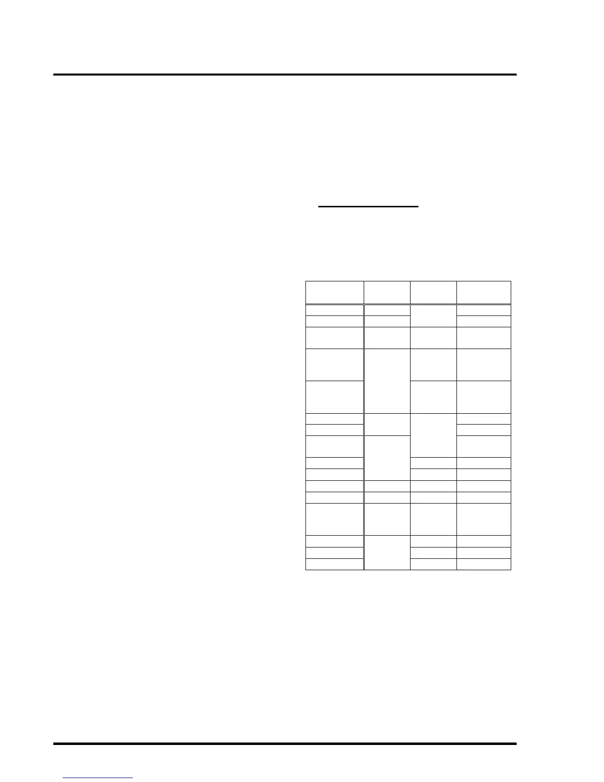
4.1 Circuit Configuration Options
Table 2 lists the available operating modes for
configurable circuits:
Table 2 – Circuit Modes