Introduction
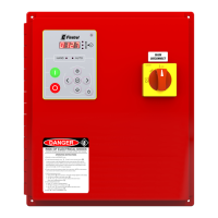
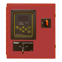
Firetrol FTA560 Jockey Pump Controllers are intended for use with fire pump systems. They
are used for pressure maintenance in fire pump installations to prevent unnecessary cy-
cling of the main fire pump.
Firetrol Jockey Pump Controllers are listed by Underwriters’ Laboratories, Inc., in accor-
dance with UL508, Standard for Industrial Controllers, and CAS, Standard for Industrial
Control Equipment. They are built to meet or exceed the requirements of the approving
authorities as well as NEMA and the latest edition NFPA, National Electrical Code.
These instructions are intended to assist in the understanding of the installation and op-
eration of these controllers. Read the instructions thoroughly prior to connecting or oper-
ating the controller. If there are any unanswered questions, please contact the local Firet-
rol representative or the factory service department.
Mounting Controller
NOTE- Consult the appropriate job plans to determine the controller mounting location.
Tools and materials (all mounting) required:
1. Assortment of common hand tools of the type used to service electromechanical
equipment.
2. Drill for drilling wall anchor holes.
3. Hole (conduit) punch.
4. Hand level.
5. Tape measure.
6. Four anchors with bolts and washers, per enclosure.
Procedure-
Note- Refer to the controller dimension drawing for necessary mounting dimensions.
The controller is wall mounted by using at least four (4) wall anchors, 2 anchors for the top
mounting brackets and 2 anchors for the bottom mounting brackets. The brackets are
dimensionally on the same centerline for ease in mounting.
1. Using either the dimension print or by measuring the distance between the center
lines of the lower bracket slots, transcribe this dimension on to the wall. Note: The
bottom edge of the enclosure should be a minimum of 12” (305mm.) from the floor in
case flooding of the pump room occurs.
2. Drill and put anchors into the wall for the lower mounting brackets.
3. Mark on the wall, the location of the holes in the upper mounting brackets.
4. Drill and put anchors into wall for the upper mounting brackets.
5. Install bolts and washers in lower anchors.
6. Align holes in upper mounting brackets and install bolts and washers in anchors.
7. Shim anchors as necessary to ensure rear of enclosure is vertical level and enclosure
is not stressed. Tighten all anchor bolts.
8. Check to be sure enclosure door open and closes freely and that enclosure is level.
2