12
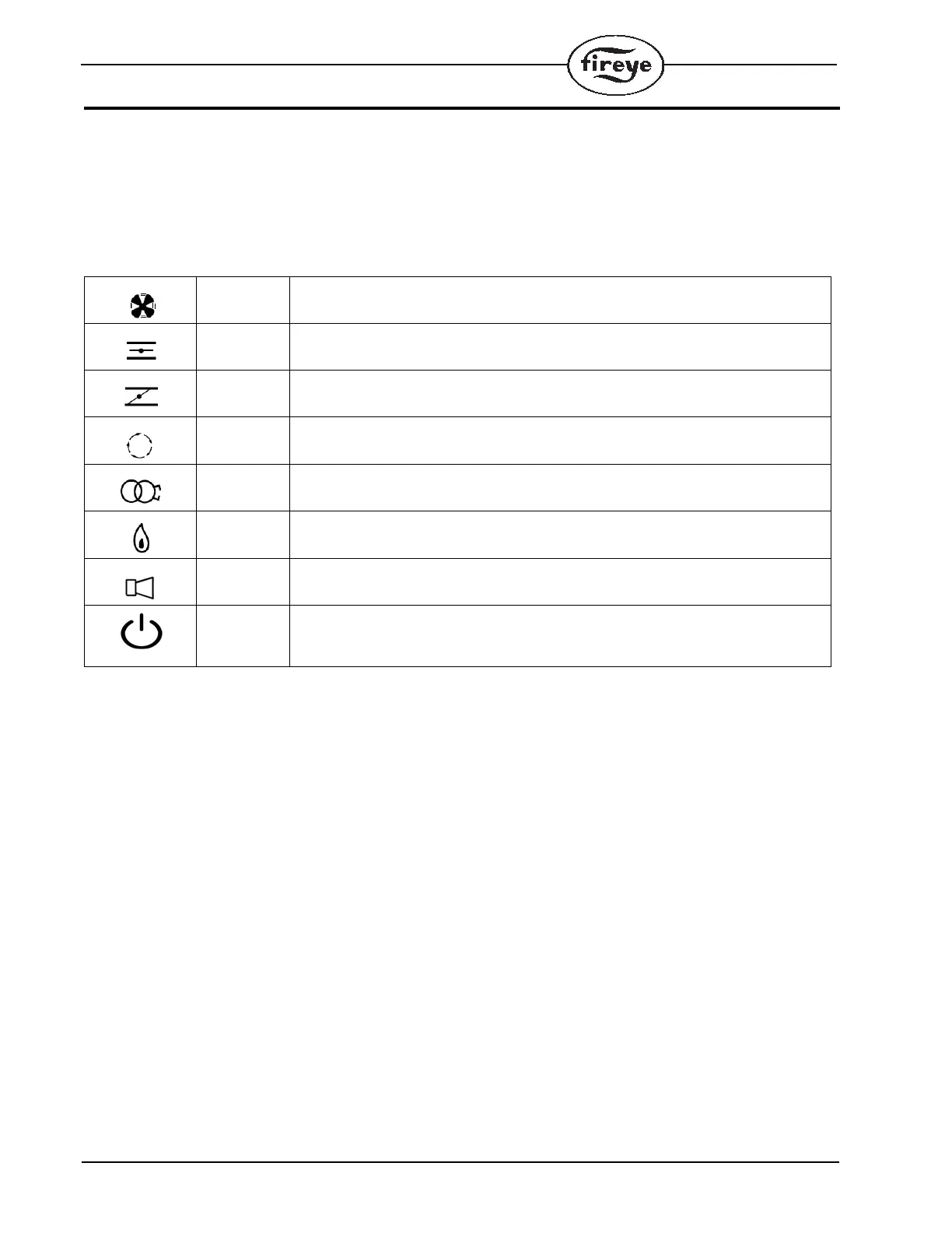
LED INDICATORS
The BurnerPRO control module has seven (7) LED indicator lights to annunciate the operating status of the
control, as well as provide the reason for the last lockout condition. The "Open Damper" and "Close
Damper" LEDs provide easy set-up of the modulating motor end switches. Each LED has a graphic symbol
to describe its function (see Table below).
Table 5: Status LEDs
The “SMART” LEDs provide a flame strength display during check mode. In check mode, the status LED is yellow,
the fan LED is blinking and LEDs 2-6 grow up from status forming a bar graph. Each LED lit represents 20% of the
total flame signal. See Table 6, Note 1. (5 LEDs lit is 100%, 2 LEDs is 40%)
FAN
Lights when the blower motor is energized (terminal 6) and flashes when the RUN/CHECK switch is in the
“CHECK” position during Minimum, Open, PTFI, and MTFI.
OPEN
DAMPER
Will blink when the modulator motor is being driven to the high fire position. Once the high purge switch
closes, this LED will light constant. The LED provides the status of the purge sequence.
CLOSE
DAMPER
Will blink when the modulator motor is being driven to the low fire position. Once the low fire switch closes,
this LED will light constant. This LED provides the status of the low fire start interlock circuit.
AUTO Will light when the control releases to automatic modulating control.
IGNITION Will blink during Pilot Trial For Ignition (PTFI). Will light constant during Main Trial For Ignition (MTFI).
FLAME Will light whenever flame is detected by the flame scanner.
ALARM
In the event of a lockout condition, the Alarm LED is illuminated and the remaining LEDs will light up to indicate
the lockout condition. See “Safety Lockout Codes.”
RESET
During normal operation, the Reset LED is GREEN. In the event of a lockout condition, the Reset LED is illumi-
nated RED. When Modbus is made, the Reset LED is illuminated YELLOW.
 Loading...