13
®
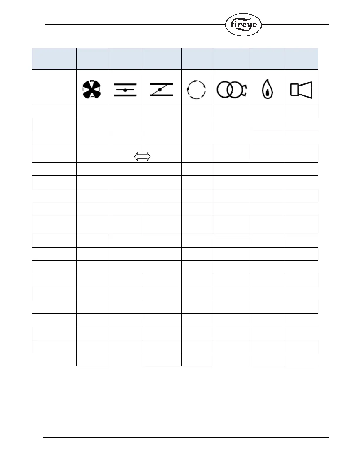
Table 6: LED Run-time Status Indicator
NOTES:
1.The LEDs form a progress bar indicating Flame Signal Strength for aiming sensors during commissioning (The LEDs “Grow”
upwards away from Status at 20% intervals of flame strength.)
2.The LEDs indicate the error or lockout code for troubleshooting
3.The LEDs change from ON to BLINKING to OFF showing the modulator operation
OPERATION
LED ● = ON
FAN
OPEN
DAMPER
CLOSED
DAMPER
AUTO IGNITION FLAME STATUS
ICON
OFF / NO
POWER
OFF
NOT READY /
DIAGNOSTICS
Green
READY /
STANDBY
● Green
CHANGING
(note 3)
●
OFF
Blinking
●
●
Blinking
OFF
Green
WAITING TO
CLOSE
Blinking
Green
Green
OPEN
(before ignition)
●● Green
MINIMUM
(before ignition)
●● Green
IGNITION ●●●Green
PTFI ●●●
Blinking
Green
Green
MTFI ●● ●Green
AUTO ●●●Green
MINIMUM
(During Flame)
●● ●Green
OPEN
(During Flame)
●● ●Green
ECONOMY ●● Green
CHECK
OPEN
Blinking ● Yellow
CHECK
MINIMUM
Blinking ● Yellow
CHECK
PTFI/MTFI/AUTO
Blinking ● Note 1 ● Note 1 ● Note 1 ● Note 1 ● Note 1 Yellow
FAULT /
LOCKOUT
● Note 2 ● Note 2 ● Note 2 ● Note 2 ● Note 2 ● Note 2 Red
END OF CYCLE ●●●●Green
 Loading...