36
This setup requires that the gas pressure switches be adjusted to levels closer to the high and low pressure
windows. Thus, allowing for the detection of trace amount of gas leakage and it also reduces the overall TEST
times. The rule of operation is similar to the single pressure switch setup: The pressure switch will "make"
(T15 high) when gas pressure in the test section exceeds the high side set pressure; it will "break" (T12 high)
when the gas pressure falls below the low side set pressure.
Pressure Switch Selection
1. Determine the maximum inlet pressure for the upstream valve.
2. For method 1, divide the inlet pressure by 2 (50%) and select a gas pressure switch that will trip at the half-
way point. For adjustable type pressure switches, adjust the setting to the desired trip point.
3. For method 2, determine the trip point for the high and low side pressure. Select pressure switches to satisfy
the high and low side pressure settings. For adjustable type pressure switches, adjust the setting to the desired
trip point.
Proper hookup of terminal 12 & 15 inputs are required in order to properly operate the valve proving feature.
The BurnerPRO is designed to allow valve proving to be performed at the beginning or at the end of a burner
cycle. BurnerPRO supports valve proving for 2-valve system, which consist of an upstream and a downstream
gas shutoff valves and the test gas is evacuated into the combustion chamber.
During the valve proving operation, the test section of the gas train is pressurized and evacuated in a method-
ical fashion. During the test sequence, the BurnerPRO allows the test section to be pressurized for 3 seconds
and evacuated for 3 seconds. The pressurization or evacuation time cannot be adjusted.
TEST TIMES 1 & 2 are programmed for 30secs. It is possible to make adjustment to the test times, but such
adjusted must be made by a qualified personnel.
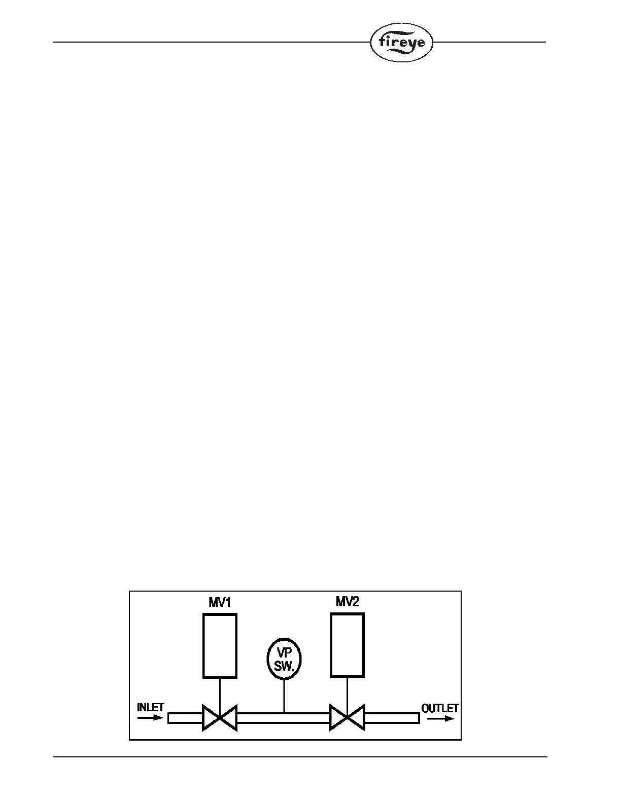
The wiring for the valve proving system is as follows:
Upstream Shutoff valve (MV1) should be wired to T18
Downstream Shutoff valve (MV2) should be wired to T19
Gas pressure switch NC position should be wired to T12
Gas pressure switch NO position should be wired to T15
2-Valve system:
Two valves (MV1 and MV2) are cycled to prove that neither gas valve leaks above an acceptable rate using
the following method described below:

 Loading...