8
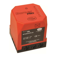
FIGURE 1.
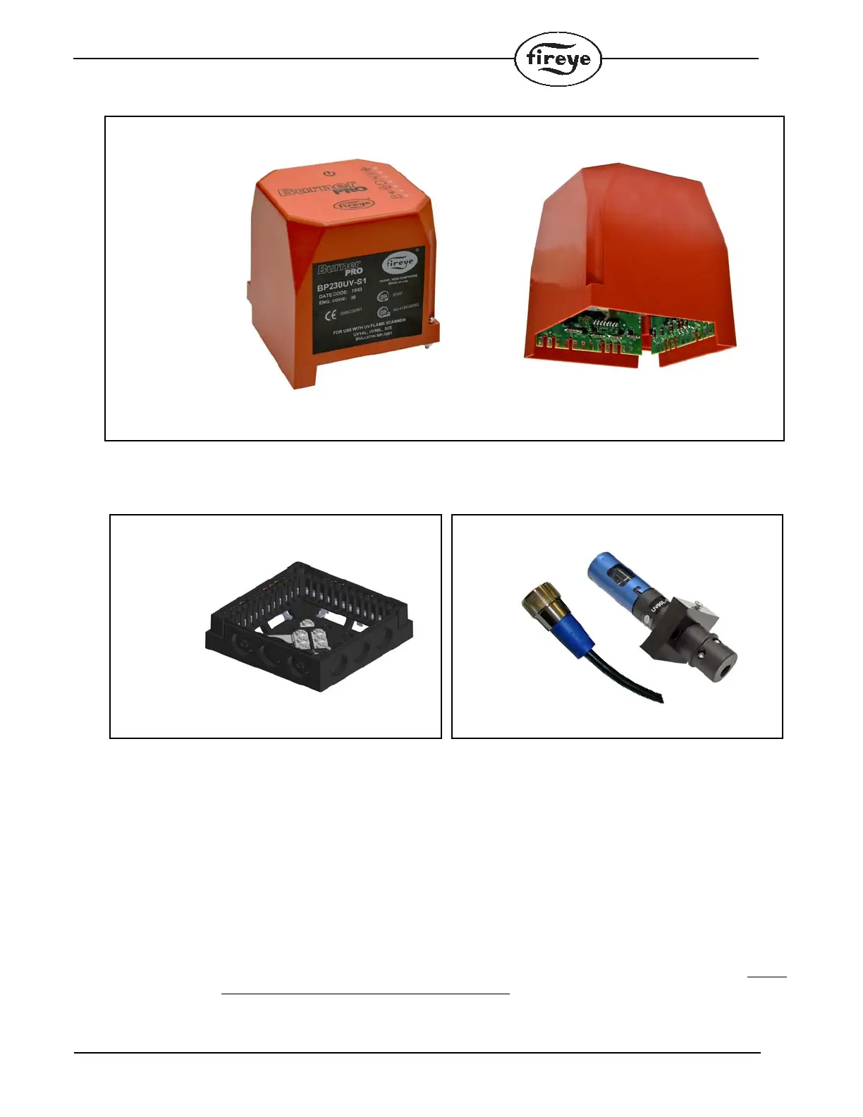
MOUNTING RECOMMENDATIONS
Wiring Base
Mounting of the base can be accomplished with 2 screws. The recommended screw sizes are #10
PAN HD x 5/8inch (5mm PAN HD x 16mm) and #10 PAN HD x 3/8 inch (5mm PAN HD x 10mm).
Refer to Figure 2 for mounting dimensions.
Grounding Wire
Each BurnerPRO control is fitted with a grounding wire. Attach the open end of the grounding wire
to a ground terminal on the wiring base (see figure 2 below). Undo the screw terminal with a screw-
driver and place the ground lug over the terminal. Re-install the screw over the ground lug. Do not
attach the grounding wire to a Neutral (N) terminal.
BOTTOM VIEW
CHASSIS/AMPLIFIER
110 VAC, 50/60 Hz
BP110UVFR-Sxxx
230 VAC, 50/60 Hz
BP230UVFR-Sxxx