10
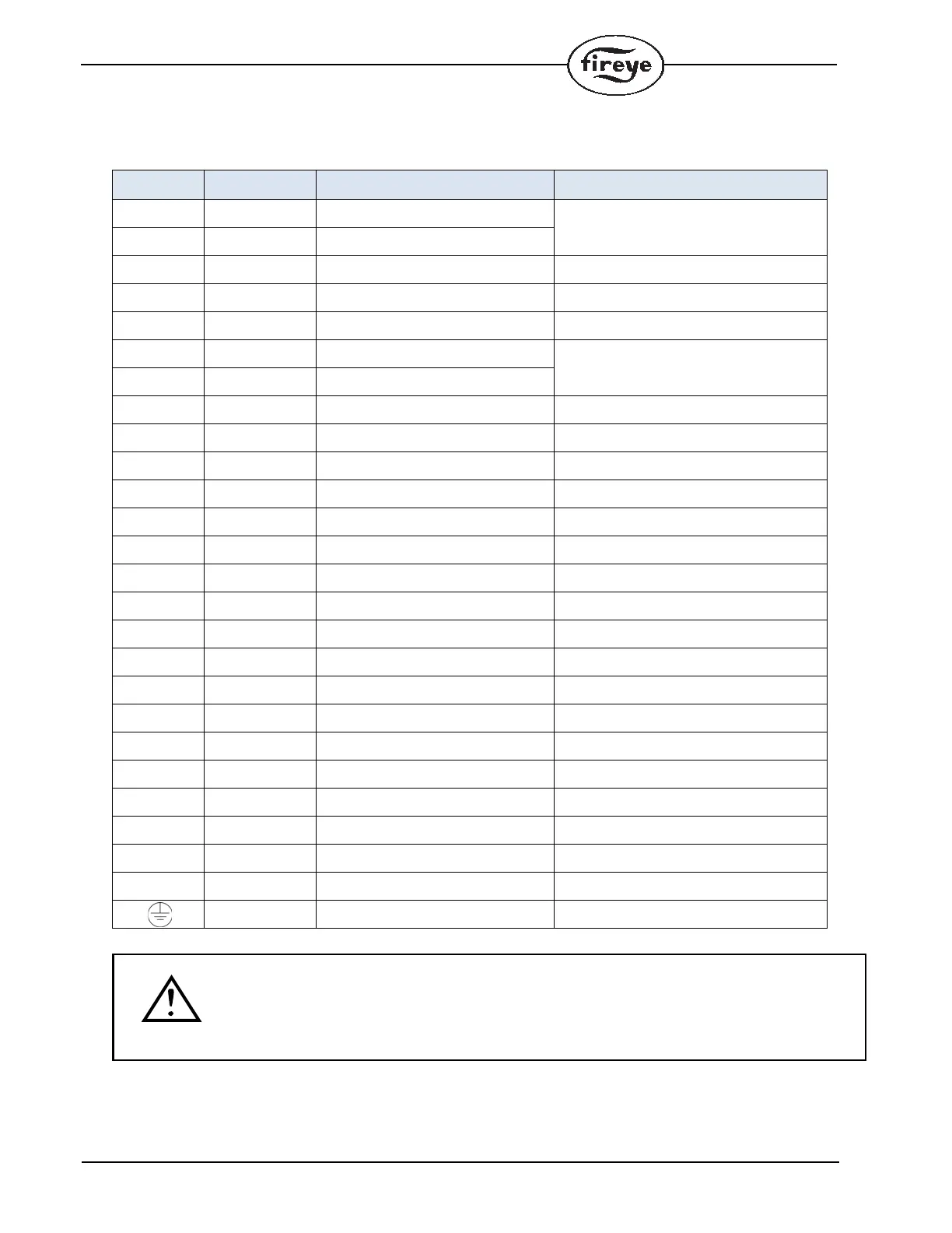
TABLE 4: TERMINAL WIRING
Terminal No. Type Description Rating
1 Power Line voltage supply
110VAC (+20%, -15%), 50/60Hz
230VAC (+10%, -15%), 50/60Hz
single phase
2 Power Line voltage common
3 Output Alarm See Load Ratings
4 Output Lockout Limits 110/230 VAC, 1mA
5 Input Recycle Limits 110/230 VAC, 1mA
6 Output Combustion Air Blower
See Load Ratings
7 Output Combustion Air Blower
8 Input Actuator Feedback 110/230 VAC, 1mA
9 Output High Fire Purge (Open) See Load Ratings
10 Output Low Fire Purge (Minimum) See Load Ratings
11 Output Closed (Economy) See Load Ratings
12 Input Valve Proving / Proof of Closure 110/230 VAC, 1mA
13 Input Combustion Air Switch Test 110/230 VAC, 1mA
14 Input Combustion Air Prove 110/230 VAC, 1mA
15 Input Valve Proving / Special function 110/230 VAC, 1mA
16 Output Ignition See Load Ratings
17 Output Pilot See Load Ratings
18 Output Main Fuel Valve 1 (MV1) See Load Ratings
19 Output Main Fuel Valve 2 (MV2) See Load Ratings
20 Output Release to Modulate (AUTO) See Load Ratings
21 Input Remote Reset 110/230 VAC, 1mA
22 Output UV Sensor (S1) 300 VDC, 3mA
23 Input UV Sensor (S2) Sensor Common/return
24 Output FR Sensor (S3) 300 VAC, 1mA
N Power Line Voltage Common
Earth Ground
CAUTION: Published load ratings assume that no contact be required to handle inrush cur-
rent more often than once in 15 seconds. The use of control switches, solenoid, relays, etc.
which chatter can lead to premature failure. It is important to run through a test operation
(with fuel shut off) following the tripping of a circuit breaker, a blown fuse, or any known
instance of chattering of any external current consuming devices.
 Loading...