15
®
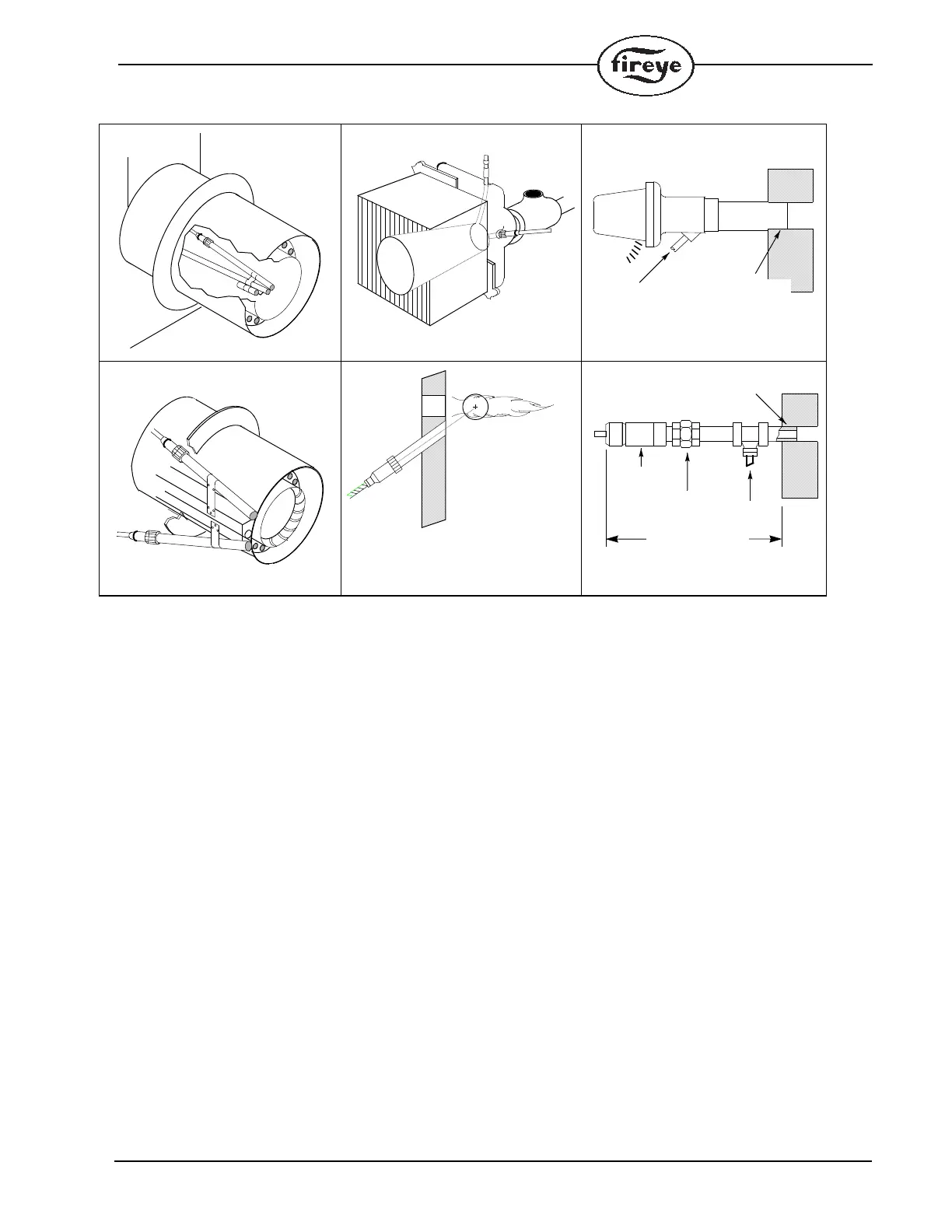
TYPICAL SCANNER INSTALLATIONS
WIRING - UV SCANNERS
To connect the scanner to the control, the UV1AL scanner is supplied with 36" or 72"
(0.9 m or 1.8 m) of flexible cable. The UV90L is supplied with a terminal board. Use two #18 AWG
conductors to connect the UV90L to the control. The UV5 is supplied with 80” (2m) of flexible cable
(detachable).
If it is necessary to extend the scanner wiring, the following instructions apply:
There is no polarity associated with the scanner wiring. Scanner wires must be installed in a separate
conduit. The wires from several scanners may be installed in a common conduit.
1. Selection of Wire
a. Wiring: For extended scanner wiring up to 500 feet (152 M), and for shorter lengths to reduce
signal loss, use a shielded wire (Belden 8254-RG62 coaxial cable, or equal) for each scanner
wire. The ends of the shielding must be taped and not grounded.
b. Avoid asbestos insulated wire.
c. Multi-conductor cable is not recommended without prior factory approval.
2. High voltage ignition wiring must not be installed in the same conduit with flame detector wires.
The maximum UV signal
from a flame is found in the
first one-third of the visible
flame taken from the point
where the flame begins. The
scanner sight pipe is aimed
at this area.
DO NOT EXTEND
MORE THAN
HALF-WAY INTO
REFRACTORY
SCANNER
FORCED
CLEAN AIR
(FROM DISCHARGE
OF FAN)
METHODS OF COOLING SCANNER
INSULATING
TUBING
SEALING UNION
FORCED
AIR
EXTEND SIGHTING TUBE
6”(152.4) OR 8”(203.2)
DO NOT EXTEND MORE THAN
HALF-WAY INTO REFRACTORY
 Loading...