16
INSTALLATION - 69ND1 FLAME ROD
The 69NDl flame rod proves a gas pilot flame and/or main gas flame. It is a spark plug type unit. It
consists of 1/2' “NPT” mount, a KANTHAL flame rod, a glazed porcelain insulating rod holder and
a spark plug connector for making electrical connections. The 69ND1 is available in 12", 18" or 24"
(0.3m, 0.46m, 0.6m) lengths.
The flame rod may be located to monitor only the gas pilot flame or both the gas pilot and main gas
flames. Mount it with a l/2" “NPT” coupling.
The following instructions should be observed:
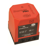
1. Keep your flame rod as short as possible.
2. Keep your flame rod at least 1/2" from any refractory.
3. Your flame rod must enter the pilot flame from the side so as to safely prove an adequate pilot
flame under all draft conditions.
4. If the flame is nonluminous (air and gas mixed before burning), extend the electrode tip at least
1/2" into the flame, but not more than halfway through.
5. If the flame is partly luminous, the electrode tip must extend only to the edge of the flame. It is
not necessary to maintain uninterrupted contact with the flame.
6. It is preferable to angle the rod downward to minimize the effect of sagging and to prevent it
from coming in contact with any object.
7. An adequate grounding surface for the flame must be provided. The grounding surface in actual
contact with the flame must be at least 4 times greater that the area of the portion of the flame
rod in contact with the flame. It is essential to adjust the flame rod and ground area ratio to pro-
vide a maximum, signal reading.
Note: Interference from the ignition spark can alter the true signal reading by adding to, or subtract-
ing from it. This trend sometimes may be reversed by interchanging the primary wires (line voltage)
to the ignition transformer. This interference can also be reduced by the addition of grounded shield-
ing between the flame rod and ignition spark.
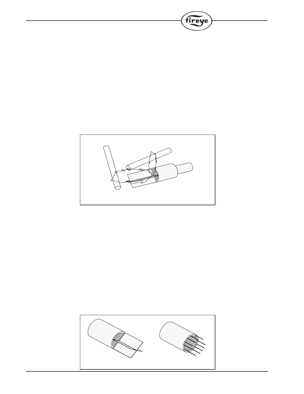
8. Proven types of flame grounding adapters, as shown below, may be used to provide adequate
grounding surface. High temperature stainless steel should be used to minimized the effect of
metal oxidation. This assembly may be welded directly over the pilot or main burner nozzle.
WRONG POSITION
OF ROD
INADEQUATE FLAME
PILOT BURNER
CORRECT POSITION
OF PILOT FLAME
CORRECT
POSITION
OF ROD
BOMB FIN GROUNDING ASSEMBLY THREADED ROD ASSEMBLY
 Loading...