Do you have a question about the Fischer Panda 8000 and is the answer not in the manual?
Essential safety instructions and warnings to prevent injury and ensure safe operation.
Detailed safety guidelines including operation, PPE, cleanliness, and handling of fuels.
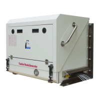
Defines the primary purpose of the generator: producing electrical energy from diesel.
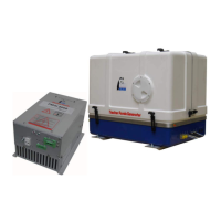
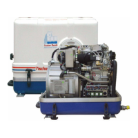
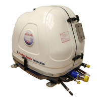
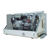
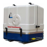
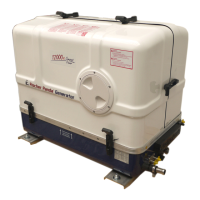
Identifies and describes the main components of the xGenerator system.
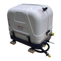
Detailed views and labels of the generator's external components from multiple perspectives.
Description of key functional units including xControl panel, cooling, fuel, and surveillance systems.
Highlights critical operational dangers, including automatic start, rotating parts, and high voltage.
General guidance for operating the generator, including considerations for low temperatures.
Details hazards during installation, including risks of injury, fire, and electrical shock.
Instructions for correctly connecting electrical wires, fuel, and cooling lines within the generator capsule.
Detailed explanation of waterlock installation, causes of water ingress, and correct positioning.
Details the ideal positioning of the waterlock to prevent water level changes in tilted positions.
Detailed instructions for connecting the starter battery, including positive and negative cable placements.
Covers crucial AC connection aspects, including protective conductors, fuses, and cable cross-sections.
Details hazards associated with maintenance, including automatic start, electrical, and fire risks.
Lists essential checks to perform before starting the generator, including oil level and leaks.
Step-by-step guide for refilling engine oil, including required tools and procedure.
Instructions for cleaning and ensuring good contact of battery terminals and cables.
Visual guide for checking the oil level using sight glasses or hoses.
Instructions for replacing the fuel filter, emphasizing correct hose connection and filter orientation.
Steps for replacing the air filter mat within the air suction housing.
Detailed steps for replacing the impeller in the raw water pump, including warnings.
Step-by-step guide for replacing the electric starter motor, emphasizing safety precautions.
Instructions for replacing the flame glow plug, including connector removal and tool usage.
Details hazards associated with troubleshooting, including automatic start, electrical, and fire risks.
Identifies causes and solutions for low generator output voltage in 50 Hz versions.
Identifies causes and solutions for high generator output voltage.
Lists potential causes and solutions for fluctuating generator voltage.
Addresses issues preventing the generator from starting an electric motor, often related to current draw.
Covers common causes and solutions when the diesel motor fails to start.
Troubleshooting steps when the starter motor turns but the engine does not start.
Critical safety procedure for checking and discharging capacitors before testing.
Steps for checking capacitor condition and functionality using a multimeter.
Procedure for testing stator winding voltage generation, including safety steps.
Explains how to restore rotor magnetism when the generator provides no voltage.
General safety instructions for the xControl system, including automatic start and electrical hazards.
Lists and describes the three main components of the Panda xControl system: CP-G, GC-S, and CB-G.
Instructions on how to switch the generator on using the ON/OFF button and the standby mode.
Explains how the overview screen indicates when autostart is enabled and its behavior.
Daily checks and preparation steps for marine versions before starting the generator.
Daily checks and preparation steps for vehicle versions before starting the generator.
Configuration steps for enabling or disabling the autostart function on the CP-G.
Configuration options for the optional DC output of the CP-G, including operation mode and follow-up time.
Setting the operational mode for the optional DC-Power output on the CP-G.
Adjusting the follow-up time for the optional DP output on the CP-G.
How to access and view the event log on the CP-G for troubleshooting.
Explains various symbols and messages displayed on the xControl for status and errors.
Example messages indicating a sensor defect detected by the xControl.
Example messages displayed when a sensor or cable is broken.
Explains how failure codes are displayed when parameters exceed specified ranges.
A table listing failure codes, descriptions, causes, warnings, and stop conditions.
| Brand | Fischer Panda |
|---|---|
| Model | 8000 |
| Category | Inverter |
| Language | English |