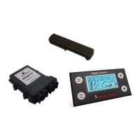
Panda xControl
Page 8 - Chapter 2: Panda xControl 29.9.16
An emergency stop device, auto-start, load relays and
boosters can be connected as options.
Note:Only electricians may work on the xControl CB-G
2.2 Installation
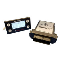
2.2.1 Installation of the Electronic Control Unit (ECU) xControl - GC-S
The ECU xControl - GC-S is pre-installed. The ECU can be exchanged easily. All connections are mechanically
coded and prevent the risk of confusion.
2.2.2 Installation of the Connection Box xControl - CB-G
The connection box is pre-installed. External components are connected in accordance with the installation manual
and the circuit diagram of the xControl generator.
2.2.3 Installation of the xControl - CP-G
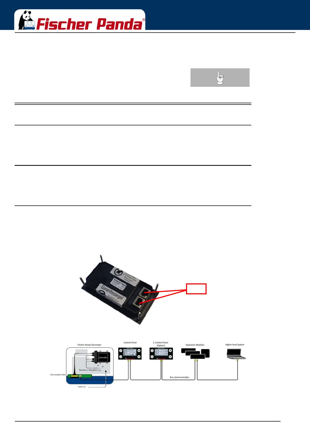
The xContol - CP-G is a CAN Bus module. All Fischer Panda CAN bus modules have two RJ45 ports. One for
connection to the module on the CAN bus, the second to relay the CAN bus. The last module on the CAN bus must
have a terminating resistor in the RJ45 port.
Connection by means of the Fischer Panda bus cable is mandatory.
Fig. 2.2-1: xControl CP-G rear
Fig. 2.2-2: Connection Diagram