20
2
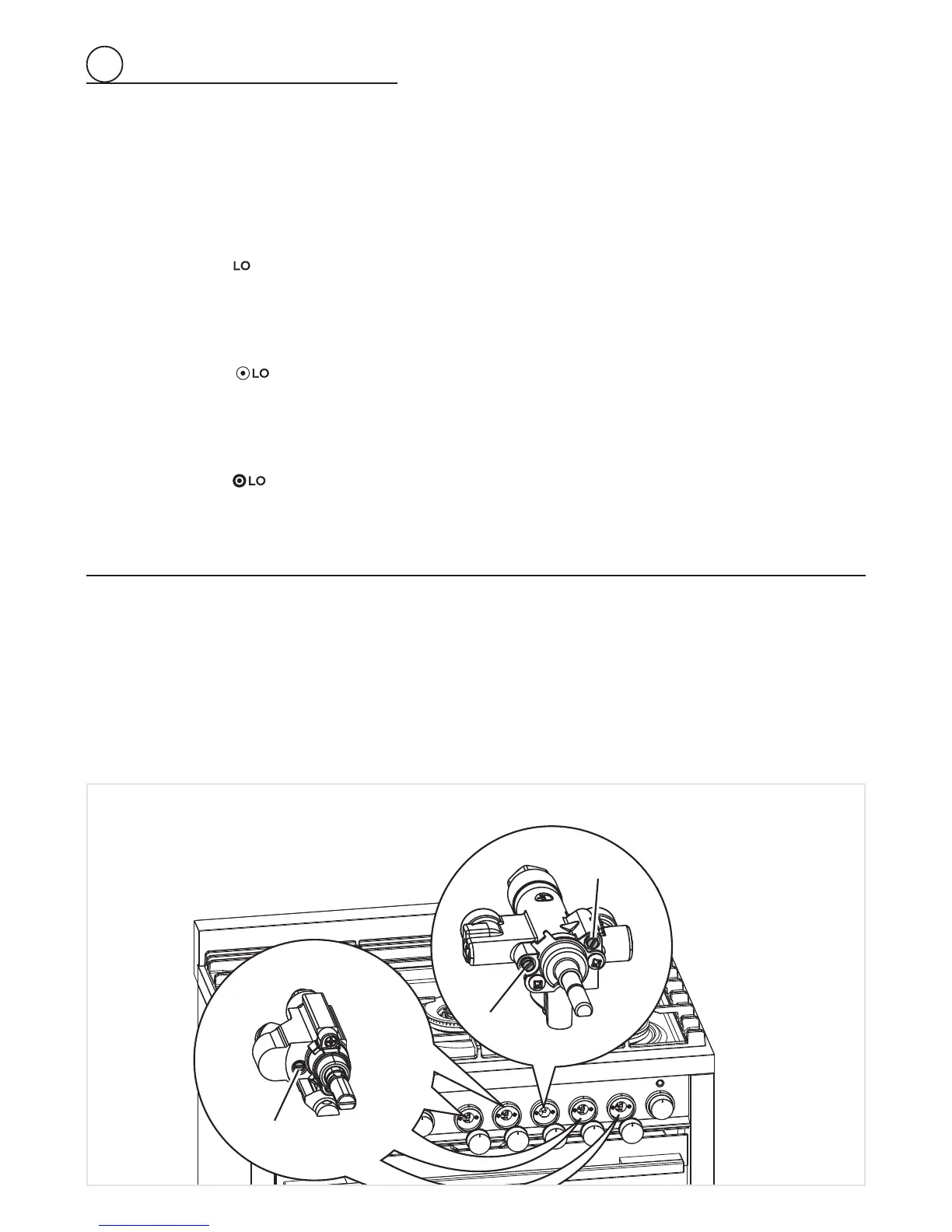
Fig. 2.14
R
1
R
3
R
2
SETTING THE BURNER MINIMUM
When switching from one type of gas to another, the minimum fl ow rate must also be correct: the fl ame should not go out even when
passing suddenly from maximum to minimum fl ame.
To regulate the fl ame (fi g. 2.14) follow the instructions below:
Triple-ring and semirapid burner
• Light the burner.
• Set the gas valve to
position (minimum rate).
• Remove the knob.
• With a thin screwdriver, turn the regulation screw “R
1
” until adjustment is correct.
Inside crown of DUAL burner
• Light the DUAL burner.
• Set the gas valve to
position (minimum rate of inner crown).
• Remove the knob
• With a thin screwdriver, turn the regulation screw “R
2
” until adjustment is correct.
Outside crown of DUAL burner
• Light the DUAL burner.
• Set the gas valve to
position (minimum rate of outer crown and maximum rate of inner crown).
• Remove the knob.
• With a thin screwdriver, turn the regulation screw “R
3
” until adjustment is correct.
For LP/PROPANE gas, tighten the adjustment screws completely.
After regulation repeat the operations indicated in paragraph “2. PRESSURE REGULATOR” at page 12 and 17.
If the range has been disconnected and then connected again to the gas supply line repeat the operations indicated in paragraph “5.
LEAK TESTING” at page 16.
IMPORTANT:
• After conversion to LP/PROPANE gas has been carried out affi x near the data plate the conversion label supplied and also affi x a
conversion label at page 3 of this instruction manual.
• After conversion back to the original gas (NATURAL GAS) has been carried out remove, near the data plate and at page 3 of this
instruction manual, the LP/PROPANE conversion labels. Save the labels removed for future use.
R
1
Regulation screw (Triple-ring and semirapid burner)
R
2
Regulation screw (Inner crown of dual burner)
R
3
Regulation screw (Outer crown of dual burner)
 Loading...