19
2
INJECTORS TABLE
NOMINAL
POWER
REDUCED
POWER
LP/PROPANE
11” W.C.P.
NATURAL GAS
4” W.C.P.
BURNERS BTU/hr BTU/hr
Ø injector
[1/100 mm]
Ø injector
[1/100 mm]
Semirapid (SR) 8000 1500 85 139
Triple-ring (TR) 12000 5000 102 170
Dual (D)
Inner crown 2800 (
1
) 1100 (
1
) 50 (
3
) 80 (
3
)
Outer crown 18000 (
2
) 6500 (
2
) 83 (x2) (
4
) 143 (x2) (
4
)
(
1
) Power calculated only with inner crown operating
(
2
) Power calculated with inner and outer crown operating
(
3
) inner crown (“J
3
” in fi gure 2.13)
(
4
) outer crown (“J
4
” in fi gure 2.13)
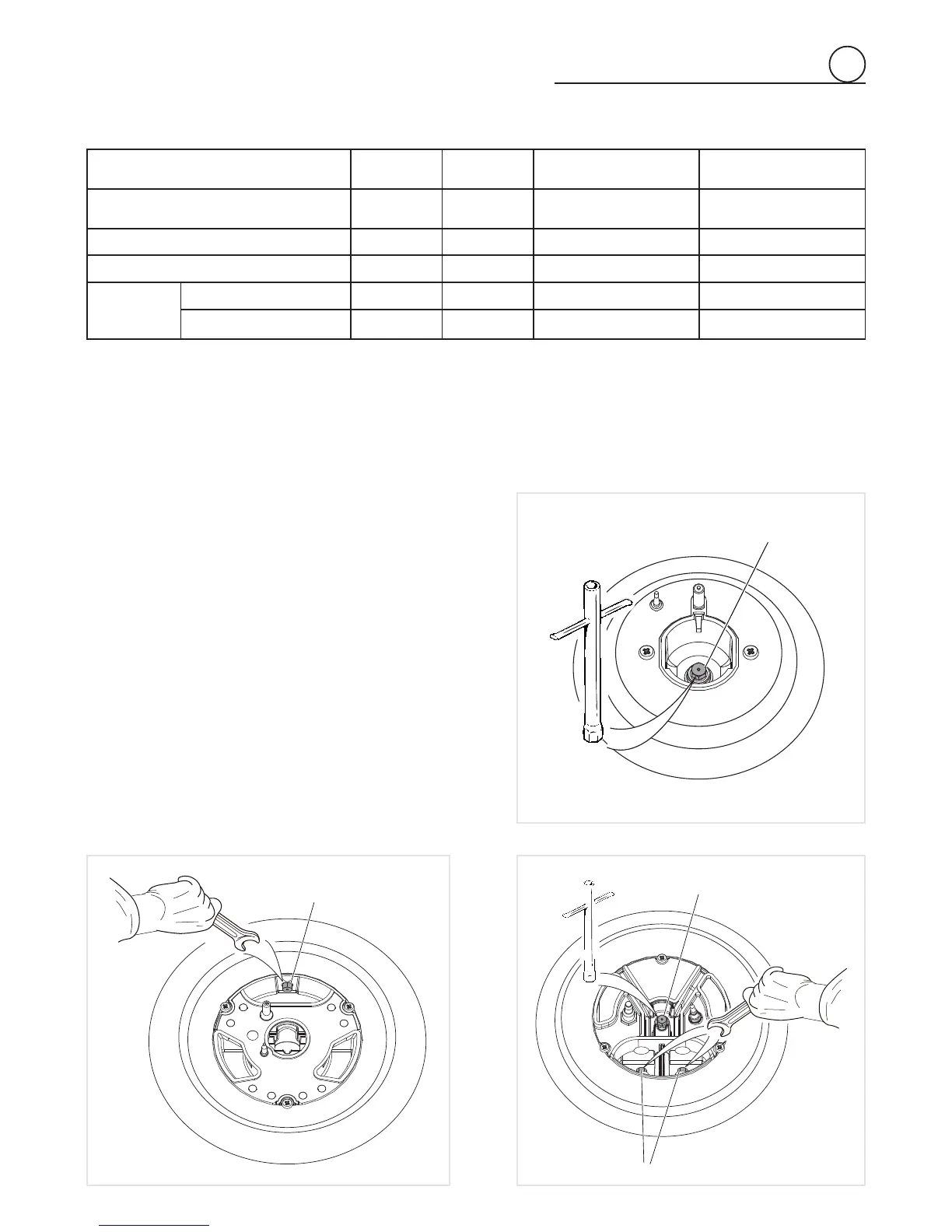
OPERATIONS TO BE PERFORMED WHEN
SUBSTITUTING THE ORIFICES
• Remove the pan supports, the burner caps and the fl ame
spreaders.
• Using a wrench substitute the nozzle injectors “J
1
”, “J
2
”,
“J
3
” and “J
4
” (fi gs. 2.11, 2.12, 2.13) with those most suita-
ble for the kind of gas for which it is to be used.
• Refi t the fl ame spreaders, the burner caps and the pan sup-
ports.
The burners are designed in such a way so as not to require
the regulation of the primary air.
J
2
J
3
J
4
Fig. 2.12 Fig. 2.13
J
1
Fig. 2.11
SEMI-RAPID BURNER
DUAL BURNERTRIPLE-RING BURNER
 Loading...