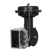
Type 1051 & 1052 Styles H & J
16
a. Read and follow the warning printed on the
nameplate (key 56) located on the diaphragm plate
(key 4).
b. Pull the diaphragm plate (key 4) and attached
parts out of the actuator. The spring (key 11), dia-
phragm rod (key 10), cap screw (key 9), spring
seat (key 13), hex nut (key 58), turnbuckle (key
57), hex nut (key 16), and rod end bearing (key 17)
will be attached to the diaphragm head.
WARNING
For Type 1051 actuators, the diaphragm
plate (key 4) may be wedged against the
diaphragm rod (key 10), thereby pre-
venting the spring compression from
being relieved as the cap screw (key 9)
is loosened. Dislodge the diaphragm
head from the diaphragm rod by loosen-
ing the cap screw (key 9) one full turn
and tapping the underside of the dia-
phragm head until it follows the cap
screw disassembly. Failure to check for
this situation before removing the cap
screw (key 9) could cause personal inju-
ry due to the sudden release of spring
compression as the cap screw is disen-
gaged.
c. Slowly remove the cap screw (key 9) while mak-
ing sure that the diaphragm head is following the
cap screw removal. Note that spring load will be
zero before the cap screw is completely removed.
Then separate the remaining parts of the assembly.
For Type 1052 actuators,
a. Remove the rod end bearing (key 17), the hex
nut (key 16), the turnbuckle (key 57), and the hex
nut (key 58) from the diaphragm rod (key 10).
b. Pull the diaphragm plate (key 4) and attached
parts out of the actuator. Then remove the cap
screw (key 9) to separate the diaphragm plate and
the diaphragm rod.
c. Proceed as appropriate:
D For actuator designs without a set screw in the
spring barrel (key 12), remove the actuator spring (key
11) from the actuator. If it is necessary to remove the
adjustor (key 74) from the spring barrel during this pro-
cedure, heat the base of the adjustor to 350_F
(177_C) long enough for the Loctite 271 thread-locking
compound (key 77) to lose its holding strength. Then,
unscrew the adjustor from the spring barrel. If the
spring seat and the lower bearing seat (key 13 and 73)
are to be replaced, unscrew the lower bearing seat
from the adjustor, and then remove the thrust bearing
and the bearing races (keys 71 and 72) from the lower
bearing seat.
D For actuator designs with a set screw (key 75),
remove the actuator spring (key 11) from the actuator.
If the spring seat and the lower bearing seat (keys 13
and 73) are to be replaced, unscrew the lower bearing
seat from the adjustor, and then remove the thrust
bearing and the bearing races (keys 71 and 72) from
the lower bearing seat. If it is necessary to remove the
spring adjustment parts, heat the set screw (key 75) to
350_F (177_C) long enough for the Loctite 271 thread-
locking compound (key 77) to lose its holding strength,
and then loosen the set screw (key 75). Unscrew the
spring adjustor (key 74) from the spring barrel (key
12).
Assembly
This procedure assumes that the actuator is complete-
ly disassembled. If the actuator is not completely dis-
assembled, start these instructions at the appropriate
step. Key numbers used are shown in figure 10 to
Type 1051 actuators and in figure 11 for Type 1052
actuators.
1. If the Type 1052 spring barrel (key 12) was re-
moved from the housing (key 10), align the spring bar-
rel to the housing as described below to ensure that
the offset hole in the base of the spring barrel is lo-
cated properly.
For size 30 actuators, note the accessory mounting
bosses on opposite sides of the spring barrel. Place
the spring barrel on the housing with one of the spring
barrel bosses on the same side as the boss located on
the housing (see figure 11). Check to be sure that the
threaded hole in the base of the spring barrel is offset
toward the positioner, or toward the cover plate (key
39) if no positioner is used. The hole is offset 7/8-inch
(22 mm) from the center of bolt circle of the four
mounting holes in the base of the spring barrel. If the
direction of offset is incorrect, rotate the spring barrel
180 degrees. Secure with the cap screws (key 21).
For size 40 and 60 actuators, note that one of the ac-
cessory mounting bosses on the spring barrel is closer
to the diaphragm end of the spring barrel. Place the
spring barrel on the housing with the upper boss (the
one closer to the diaphragm end) on the same side as
the boss located on the housing (see figure 11). This
ensures proper positioning of the offset hole. Secure
the spring barrel with the cap screws (key 21).
For size 70 actuators, the spring barrel need not be
aligned in any particular position when placing it on the
housing.

 Loading...