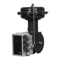
Type 1051 & 1052 Styles H & J
3
Table
2. Output Shaft Diameters and T
orque Limits for
Actuators With H Mounting
ACTUATOR
OUTPUT SHAFT
DIAMETER
TORQUE LIMIT FOR
H MOUNTING
SIZE
Inches mm Inch-Pounds
NDm
30
7/8
1-1/8
22.2
28.6
2120
2120
240
240
40
7/8
1-1/8
1-1/2
22.2
28.6
38.1
2120
4140
9815
240
468
1110
60
1-1/8
1-1/2
2
(2)
28.6
38.1
50.8
4140
10,680
23,430
468
1210
2650
70
(1)
1-1/2
2
(2)
38.1
50.8
10,680
23,430
1210
2650
1. Type 1052 actuator only.
2. Coupling supplied for mating with either 1-3/4 or 2-inch (44.5 or 50.8 mm) keyed
shaft.
diameters and torque limits are listed in table 2. Di-
mensional information for the mounting plate and out-
put shaft are shown in figures 4 and 5.
The J mounting adaptation permits the actuator to be
used for rotary actuation of Fisher keyed-shaft butter-
fly valve bodies and other keyed-shaft equipment. This
mounting adaptation uses the standard butterfly valve
mounting bracket and provides an output shaft with an
attached coupling for keyed equipment shafts. Cou-
pling sizes and torque limits are listed in table 3. Di-
mensional information for the mounting yoke and stub
shaft coupling is shown in figures 4 and 5.
Additionally with Type 1051 and 1052 actuators, the
top-mounted handwheel can be applied for infrequent
service as a manual handwheel actuator. For more
frequent manual operation, a side-mounted handwheel
actuator is available. Also, an adjustable up travel stop
can be added to limit the actuator stroke in the upward
direction, or an adjustable down travel stop can be
added to limit actuator stroke in the downward direc-
tion.
Specifications
Specifications are shown in table 1 for Type 1051 and
1052 actuators. Specifications for a given Type 1051
or 1052 actuator as it originally comes from the factory
are stamped on a nameplate (figure 3) attached to the
actuator.
Installation
WARNING
To avoid personal injury or property
damage caused by bursting of pressure-
retaining parts, be certain the dia
Table
3. Acceptable Shaft Diameters and T
orque Limits for
Actuators With J Mounting
ACTUATOR
SIZE
COUPLING
AVAILABILITY BY
KEYED SHAFT
DIAMETER
TORQUE LIMIT FOR
J MOUNTING
Inches mm Inch-Pounds
NDm
30
3/8
1/2
5/8
9.5
12.7
15.9
460
610
1010
52
69
114
40
3/8
1/2
5/8
3/4
1
9.5
12.7
15.9
19.1
25.4
460
610
1010
1830
4140
52
69
114
207
468
60
3/4
1
1-1/4
1-1/2
19.1
25.4
31.8
38.1
1830
4140
9110
12,000
207
468
1030
1360
70
(1)
1-1/4
1-1/2
31.8
38.1
9110
12,000
1030
1360
1. Type 1052 actuator only.
Figure
3. Nameplate Used on T
ype 1051 and 1052 Actuator
16A3188-G Sht 2/DOC
phragm casing pressure does not ex-
ceed the diaphragm casing pressure
limits listed in table 1. Use pressure-lim-
iting or pressure-relieving devices to
prevent the diaphragm casing pressure
from exceeding these limits.
Actuator Mounting
Use the following steps to connect the actuator to a
valve body or other equipment. Unless otherwise spe-
cified, key numbers are shown in figures 10 and 11.
Mounting dimensions are shown in figures 4 and 5.

 Loading...