Type 2500
4
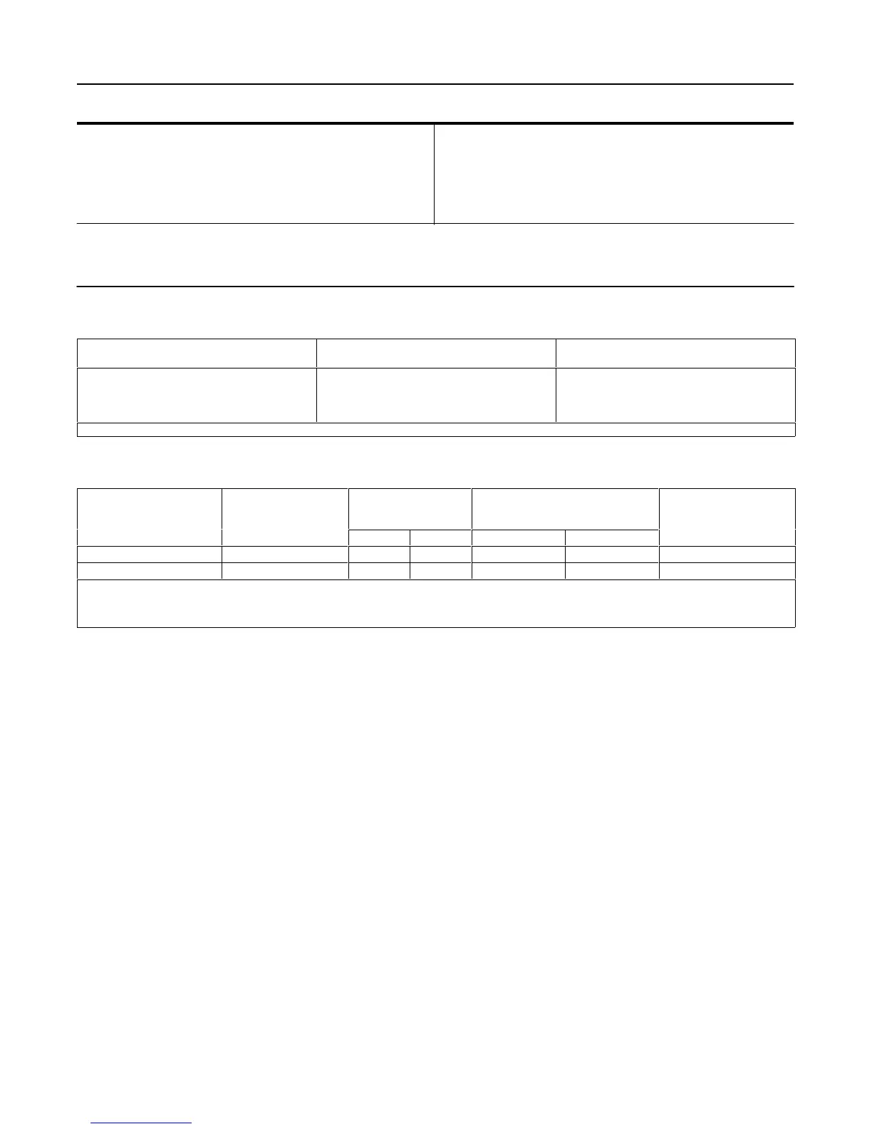
Table 1. Specifications (Continued)
Typical Ambient Temperature Operating Influence
Output pressure changes 1.5% per 50F
(10C)change in temperature at 100% proportional
band when using a standard wall torque tube with
249 Series sensors.
Supply and Output Connections
1/4-inch NPT female
Maximum Working Pressure (sensors only)
Refer to the appropriate sensor instruction manual.
1. Controllers are field adjustable between direct or reverse action. The letter R in the type number indicates that the controller/transmitter shipped from the factory set for reverse action (see
changing controller action procedures). The letter C in the type number indicates that a pointer is attached to the torque tube shaft providing visual monitoring of torque tube motion.
2. This term is defined in ISA Standard S51.1-1979.
3. Control and stability may be impaired if the maximum pressures are exceeded.
4. Adjusting the span of the differential gap controller is equivalent to adjusting the deadband.
5. These statements apply only to units sized to produce a full output change for a 100% level change at the maximum proportional band dial setting.
Table
2. Standard Displacer Volumes
SENSOR TYPE
STANDARD VOLUME,
Cubic Inches
STANDARD VOLUME,
Liters
249, 249B, 249BP, 249K, 249N
249C, 249CP
249L
249V
100
60
120
80
(1)
1.6
1.0
1.9
1.3
(1)
1. With standard 12-inch (305 mm) flange-face-to-displacer centerline dimension only.
Table 3. Supply Pressure Data
OUTPUT SIGNAL RANGE
STANDARD SUPPLY
AND OUTPUT
PRESSURE GAUGE
NORMAL OPERATING
SUPPLY PRESSURE
(2)
AIR CONSUMPTION AT
NORMAL OPERATING
SUPPLY PRESSURE
MAXIMUM
SUPPLY PRESSURE
INDICATIONS
(1)
Psig Bar Minimum
(3)
Maximum
(4)
3 to 15 psig (0.2 to 1 bar) 0 to 30 psig 20 1.4 4.2 scfh
(5)
27 scfh
(5)
45 psig (3 bar)
6 to 30 psig (0.4 to 2 bar) 0 to 60 psig 35 2.4 7 scfh
(5)
42 scfh
(5)
45 psig (3 bar)
1. Consult your Fisher Controls representative about gauges in other units.
2. Control and stability may be impaired if this pressure is exceeded.
3. At zero or maximum proportional band or specific gravity setting.
4. At setting in middle of proportional band or specific gravity range.
5. If air consumption is desired in normal m
3
/hr at 0C and 1.01325 bar, multiply scfh by 0.0258.
 Loading...


