Type 2500
8
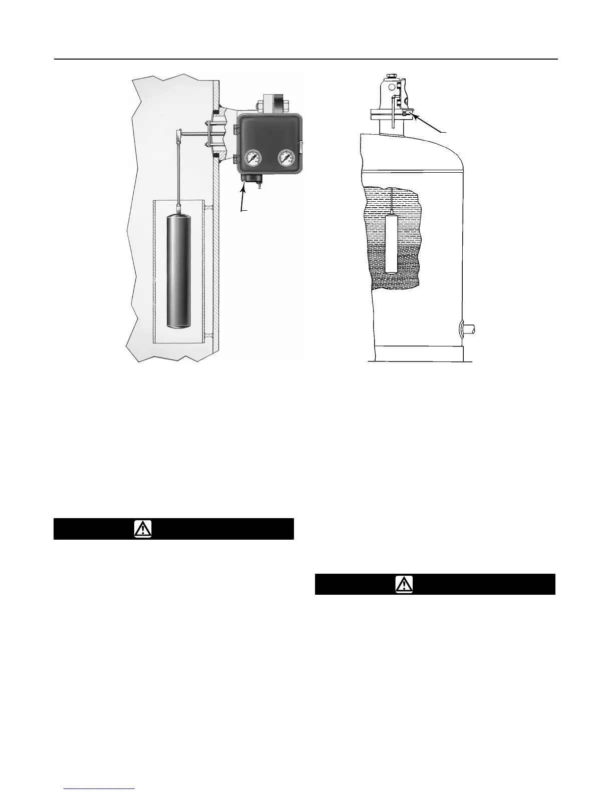
Figure
7. Cageless Sensor Mounting
CF5380-A
A3893/IL
TOP
MOUNTED
SIDE
MOUNTED
W0645–1/IL
If an extension is used between the displacer spud
and the displacer stem end piece, make sure the nuts
are tight at each end of the displacer stem extension.
Install and tighten suitable bolting or cap screws in the
flanged connection to complete the installation.
Top-Mounted Sensor
CAUTION
If inserting the displacer into the vessel
before attaching to the displacer rod,
provide a means of supporting the dis-
placer to prevent it from dropping into
the vessel and suffering damage.
Figure 7 shows an example of a top-mounted cage-
less sensor. You may attach the displacer to the dis-
placer rod before installing the sensor on the vessel. If
the displacer diameter is small enough, you may de-
sire to install a long or sectionalized displacer through
the sensor head access hole after the sensor is
installed on the vessel. Connect the displacer as
shown in figure 8, locking the assembly with the cotter
springs provided. If a stem extension is used between
the displacer spud and the stem end piece, make sure
the nuts are tight at each end of the stem. Install and
tighten suitable cap screws in the flanged connection
to complete the installation.
A special travel stop may be provided on top-mounted
sensors to aid in servicing of the sensor. This option
prevents dropping the displacer and stem when the
displacer rod is disconnected
Special Installations
Temperature-Compensated Displacer
CAUTION
The bellows style temperature compen-
sating displacers are relatively fragile
and must be protected from all physical
damage.
Some sensor assemblies use a temperature-compen-
sated displacer shown in figure 9. This displacer is
appropriate only for density applications that measure
fluid composition regardless of temperature. The dis-
placer must be filled completely with the fluid to be
measured, or with a fluid of equal volumetric expan-
 Loading...


