Type 2500
6
Figure
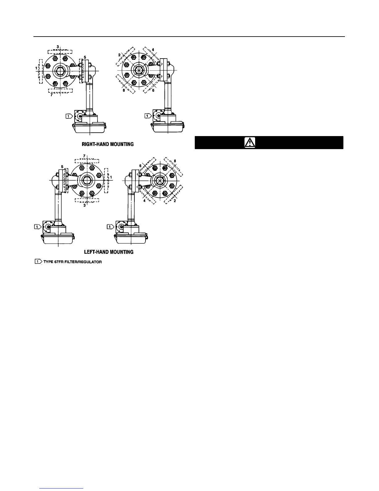
4. Cage Head Mounting Positions
AH9150–A
A2613–1/IL
A cageless sensor comes with its displacer separated
from the sensor assembly. Displacers longer than 32
inches (813 mm) come in a separate crate. Shorter
displacers come in the same crate as the sensor, but
are not attached to their displacer rods. Inspect the
displacer to insure it is not dented. A dent may reduce
the pressure rating of the displacer. If a displacer is
dented, replace it.
Controller/Transmitter Orientation
The controller/transmitter attaches to the sensor in
one of the mounting positions shown in figure 4. Right
hand mounting is with the controller or transmitter
case to the right of the displacer when you look at the
front of the case; left hand mounting is with the case
to the left of the displacer. The mounting position can
be changed in the field. Changing this mounting posi-
tion changes the control action from direct to reverse,
or vice versa.
All caged sensors have a rotatable head. That is, the
controller/transmitter may be positioned at any of eight
alternate positions around the cage as indicated by the
numbers 1 through 8 in figure 4. To rotate the head,
remove the head flange bolts and nuts and position
the head as desired.
Mounting Caged Sensor
CAUTION
Install the cage so that it is plumb; the
displacer must not touch the cage wall.
If the displacer touches the cage wall,
the unit will transmit an erroneous out-
put signal.
Note
If the controller/transmitter is not
mounted on the sensor, refer to the
Installing Controller/Transmitter on Sen-
sor procedures in the Maintenance sec-
tion. That section also provides instruc-
tions for adding a heat insulator to a
unit.
If a temperature-compensated displacer
or piezometer ring is used, refer to the
Special Installation procedures in this
section before proceeding.
Cage connections normally are either 1-1/2 or 2-inch,
screwed or flanged. Figure 5 shows the combinations.
With flanged connections, use standard gaskets or
other flat-sheet gaskets compatible with the process
fluid. Spiral-wound gaskets without compression-con-
trolling centering rings cannot be used for flange con-
nections.
As shown in figure 6, mount the cage by running
equalizing lines between the cage connections and the
vessel. A shutoff or hand valve with a 1-1/2 inch diam-
eter or larger port should be installed in each of the
equalizing lines. Also install a drain between the cage
and shutoff or hand valve whenever the bottom cage
line has a fluid-trapping low point.
On fluid or interface level applications, position the
sensor so that the center line on the cage (see figure
6) is as close as possible to the center of the fluid level
or interface level range being measured. Also consider
installing a gauge glass on the vessel, or on the sen-
sor cage (if the cage is tapped for a gauge).
 Loading...


