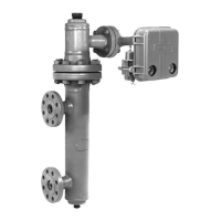
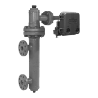
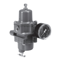
Type 2500
21
The following descriptions explain how the relay action
produces the output signal with the various controller/
transmitter constructions.
Type 2500 Controller or 2500T
Transmitter
Full supply pressure comes to the relay from the regu-
lator, as shown in figure 14. The relay has a fixed re-
striction through which supply pressure bleeds before
entering the large diaphragm area and the inner Bour-
don tube channel. In a steady-state condition, the pro-
cess level holds the torque tube and attached flapper
steady in relation to the nozzle. This allows pressure
to escape between the nozzle and flapper at the same
rate it bleeds into the large diaphragm area. The large
diaphragm holds the inlet end of the relay valve slight-
ly open to compensate for the venting of output pres-
sure through the proportional valve as it maintains a
steady-state position of the final control element. The
output pressure, through the three-way proportional
valve, affects the Bourdon tube outer channel, holding
the Bourdon tube in a steady-state position.
A process level change raises or lowers the displacer,
moving the flapper with respect to the nozzle. If the
process level change increases nozzle pressure, the
large diaphragm moves down; this closes the exhaust
end and opens the inlet end of the relay valve (see
figure 14). This action of the relay valve increases the
output pressure to the final control element. Since the
area ratio of the large diaphragm to the small dia-
phragm is three-to-one, the small diaphragm action
amplifies the output pressure change. The three-way
proportional valve lets the increase in output pressure
apply to the Bourdon tube outer channel. The expan-
sion of the Bourdon tube moves the nozzle away from
the flapper slowing the response of the pneumatic cir-
cuit.
If the process level change decreases the nozzle pres-
sure, the large diaphragm moves up. This action
closes the inlet end and opens the exhaust end of the
relay valve which allows output pressure to exhaust.
This relay valve action reduces the output pressure to
the final control element and is the reverse of the pre-
vious explanation.
The proportional valve varies the reaction of the Bour-
don tube to changes in the output pressure. For addi-
tional information on the proportional valve action, re-
fer to the following proportional valve subsection.
Proportional Valve
The three-way proportional valve is adjustable to allow
some or all of the output pressure change to feed back
to the Bourdon tube outer channel, providing propor-
tional band control (see figure 14). The Bourdon tube
moves to counteract the pressure changes in the
nozzle, equaling the relay diaphragm pressure differ-
ential. The relay valve maintains a new output pres-
sure according to the change in the process variable.
A wide-open proportional valve (fully counterclock-
wise) permits feedback of the output pressure signal
change and produces 100 percent proportional re-
sponse. A closed (fully clockwise) proportional valve
produces smaller proportional responses, because
part of the output pressure change vents through the
proportional valve exhaust.
Type 2500S Controller
This construction has the same flapper, relay, and pro-
portional valve as the Type 2500 controller. However,
the nozzle is connected (figure 14) in such a way that
output pressure feedback (from the movement of the
Bourdon tube) moves the nozzle in the opposite direc-
tion of the flapper. This action completely opens the
relay valve for full output pressure or completely
closes the relay valve for full exhaust of the output
pressure, allowing no in-between throttling.
Type 2503 Controller
This construction has the same flapper and sensor
arrangement as the Type 2500 controller, but its Bour-
don tube has a three way valve operated by a plunger
(see figure 15). Note that the switch point adjustment
changes the position of the moveable arm and at-
tached Bourdon tube assembly; this in turn changes
the switch point in relationship to the process level.
The differential gap of the 2503 either completely
opens the relay valve for full output pressure or com-
pletely closes the relay valve for full exhaust of the
output pressure, allowing no in-between throttling.
For a direct-acting controller, as long as the process
variable remains above the switch point, the flapper
does not depress the plunger of the Bourdon tube
valve. In this condition, the Bourdon tube valve re-
mains closed, providing full loading pressure to the
Bourdon tube. This loading pressure moves the Bour-
don tube away from the flapper. Also, in this condition,
full loading pressure is on the upper diaphragm of the
relay. The loading pressure moves the diaphragm
down, closing the exhaust end and opening the inlet
end of the relay valve, allowing full output pressure.
When the process level sufficiently decreases, the
flapper pushes in the plunger of the Bourdon tube
valve enough to release the loading pressure and seal
the inner Bourdon tube channel (see figure 15). This
decrease in the loading pressure moves the Bourdon
tube toward the flapper, producing the snap action.
Also, this decrease in loading pressure allows relay
spring pressure to move the large diaphragm up, clos-
ing the inlet end and opening the exhaust end of the
relay valve,

 Loading...


