Type 2500
7
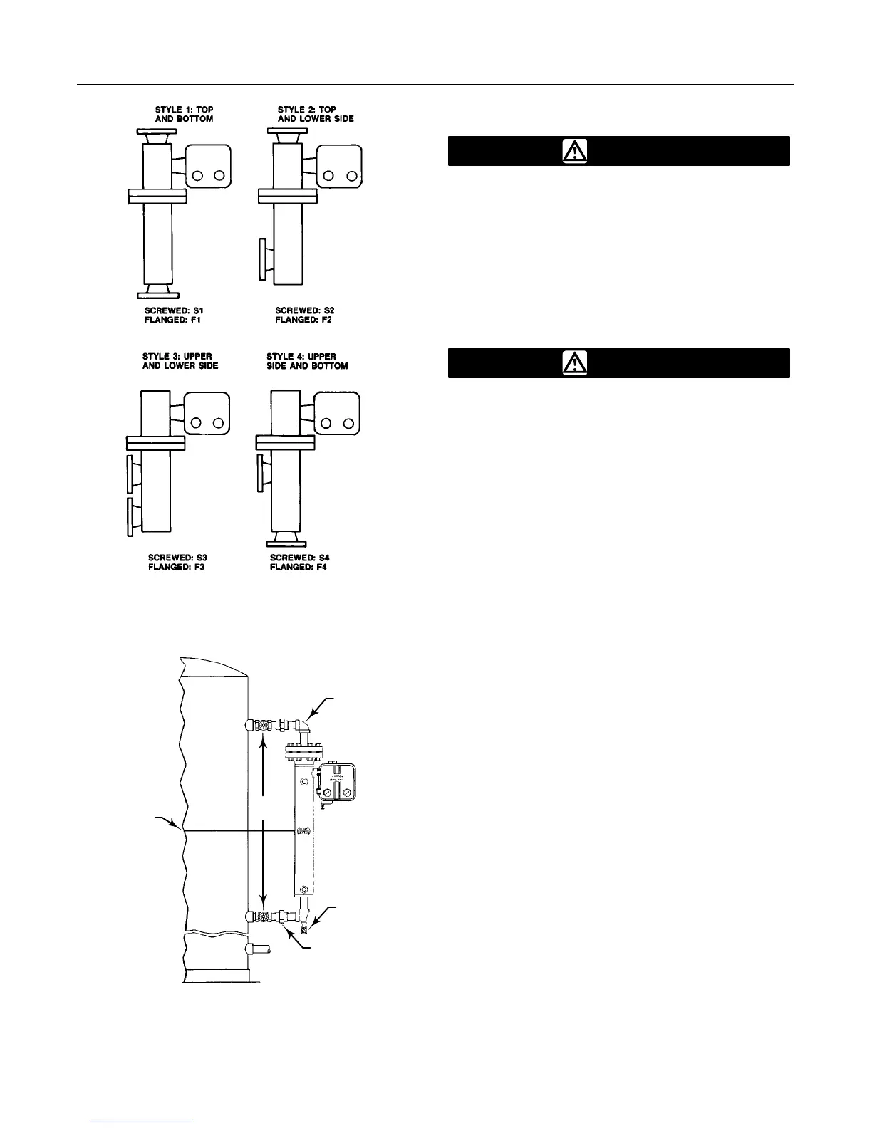
Figure
5. Cage Connection Styles
A1271–2/IL
Figure 6. Caged Sensor Mounting
EQUALIZING LINE
DRAIN VALVE
EQUALIZING LINE
CENTER OF
LIQUID OR
INTERFACE LEVEL
DF5379-A
A1883-2/IL
SHUTOFF
VALVES
Mounting Cageless Sensor
CAUTION
If a stillwell is used, install it plumb so
that the displacer does not touch the
wall of the stillwell. If the displacer
touches the wall, the unit will transmit
an erroneous output signal.
Since the displacer hangs inside the vessel, provide a
stillwell around the displacer if the fluid is in a state of
continuous agitation to avoid excessive turbulence
around the displacer.
CAUTION
Displacers used in an interface level ap-
plication must be completely sub-
merged during operation. To obtain the
desired controller or transmitter sensi-
tivity may require using either a thin-
wall torque tube, an oversized displacer,
or both.
Note
If the controller/transmitter is not
mounted on the sensor, refer to the
Installing Controller/Transmitter on Sen-
sor procedures in the Maintenance sec-
tion. That section also provides instruc-
tions for adding a heat insulator to a
unit. If the sensor has a temperature-
compensated displacer or piezometer
ring, refer to the Special Installations
procedures in this section before pro-
ceeding.
Attach a cageless sensor to a flanged connection on
the vessel as shown in figure 7. For interface or fluid
level applications, install a gauge glass on the vessel.
Side-Mounted Sensor
If a stillwell is required (see figure 7), attach the dis-
placer to the displacer rod from inside the vessel.
Connect the displacer as shown in figure 8, locking the
assembly with the cotter spring provided. If a stillwell
is not required, attach the displacer rod before mount-
ing the sensor on the vessel. Then, you can swing the
displacer out horizontally for insertion into the vessel.
However, once the sensor is installed and the displac-
er drops to a vertical position, the displacer may not
be capable of being withdrawn for servicing later. Be
sure there is another access to the displacer to permit
swinging it to a horizontal position or to permit discon-
necting it from the displacer rod.
 Loading...


