Type 2500
9
W0229-1A/IL
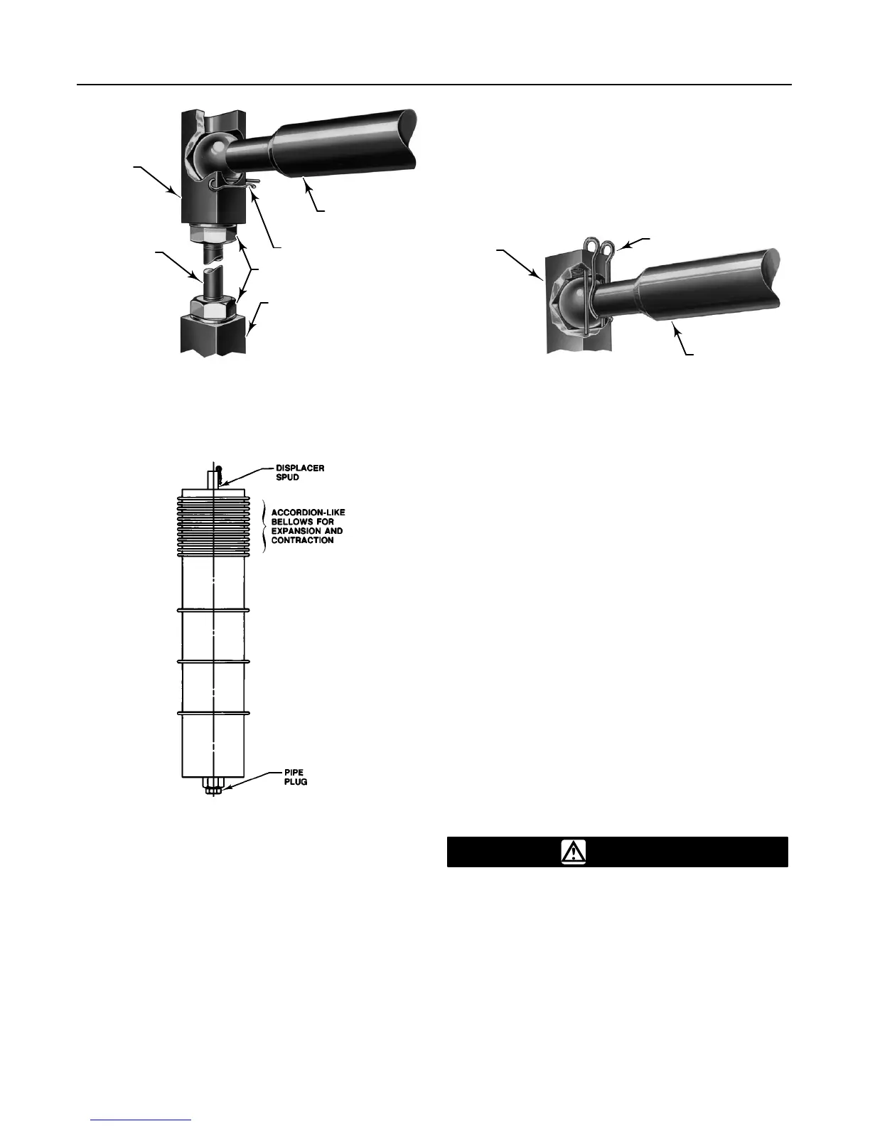
COTTER SPRING
DISPLACER ROD
LOCKING NUTS
DISPLACER SPUD
DISPLACER
STEM
EXTENSION
DISPLACER
STEM
END PIECE
W0228-1A/IL
DISPLACER ROD
DISPLACER
SPUD
COTTER SPRING
Figure
8. Displacer and Displacer Rod Connections
Figure 9. Temperature-Compensated Displacer
A0746–1/IL
sion coefficient. In service, the displacer expands and
contracts the same amount as the measured fluid to
nullify signal changes that would be caused by tem-
perature changes.
This type of displacer comes in a separate carton, but
is in the same crate as the rest of the assembly. See
the appropriate sensor manual for displacer filling
instructions.
Piezometer Ring
A piezometer ring, shown in figure 10, is used when
measuring the specific gravity of a flowing fluid in a
line. The piezometer ring reduces the velocity effects
caused by fluid passing through the displacer cage.
However, the fluid velocity through the cage should
not exceed two feet per minute (10 mm/second).
To install this type of sensor, connect a line to the
cage inlet and outlet piping at each end of the cage.
Use hand valves to balance the fluid flow through the
cage and keep the displacer cage filled. Provide a
rotameter or sight flow gauge for measuring velocity
through the cage. If the flow rates are properly bal-
anced, the transmitter output shows little change when
flow through the cage is shut off. If the flow rate
through the cage is too high, the turbulence may
cause an erratic output pressure signal. Readjust the
hand valves to stabilize the output pressure signal.
Supply and Output Pressure
Connections
WARNING
To avoid personal injury or property
damage resulting from the sudden re-
lease of pressure, do not install any sys-
tem component where service condi-
tions could exceed the limits given in
this manual. Use pressure-relieving de-
vices as required by government or ac-
cepted industry codes and good engi-
neering practices.
 Loading...


