Type 2500
5
Figure 2. Guidelines for Use of Optional Heat Insulator Assembly
0 20 40 60 80 100 120 140 160
USE INSULATOR (CAUTION! IF AMBIENT DEWPOINT IS ABOVE
PROCESS TEMPERATURE, ICE FORMATION MAY CAUSE IN-
STRUMENT MALFUNCTION AND REDUCE INSULATOR EFFECTIVE-
NESS.)
01020
–18
–10
30 40 50 60 70
71
593
500
400
300
200
100
–40
0
400
800
1100
–20
NO INSULATOR NECESSARY
AMBIENT TEMPERATURE (C)
AMBIENT TEMPERATURE (F)
HEAT INSULATOR
REQUIRED
TOO
HOT
NOTE:
FOR APPLICATIONS BELOW –20F (–29C), BE SURE THE SENSOR
MATERIALS OF CONSTRUCTION ARE APPROPRIATE FOR THE SERVICE
TEMPERATURE.
PROCESS TEMPERATURE ( C)
PROCESS TEMPERATURE ( F)
0 20 40 60 80 100 120 140 200
0
10 20
–18
–10
30 40 50 60 70
105
593
500
400
300
200
100
0
0
400
800
1100
–20
NO INSULATOR NECESSARY
AMBIENT TEMPERATURE (C)
AMBIENT TEMPERATURE (F)
HEAT INSULATOR
REQUIRED
TOO
HOT
PROCESS TEMPERATURE ( C)
PROCESS TEMPERATURE ( F)
180160
80 90
USE INSULATOR (CAUTION! IF AMBIENT DEWPOINT IS ABOVE PROCESS
TEMPERATURE, ICE FORMATION MAY CAUSE INSTRUMENT MALFUNCTION
AND REDUCE INSULATOR EFFECTIVENESS.)
CV6190–E
B1413-2/IL
–40
–29
–18
100
220
CAUTION
Sensors used for interface or density
control may be so large and heavy that
the torque tube cannot fully support
their weight in air. On the 249V, a travel
stop is used to prevent damage. Do not
remove this travel stop assembly with-
out first removing the displacer from the
displacer rod. Refer to the instruction
manual for cageless 249 Series sensors.
Note
Caged sensors have rods and blocks
installed at each end of the displacers to
protect the displacers in shipping. Re-
move these parts before you install the
sensor to allow the displacer to function
properly.
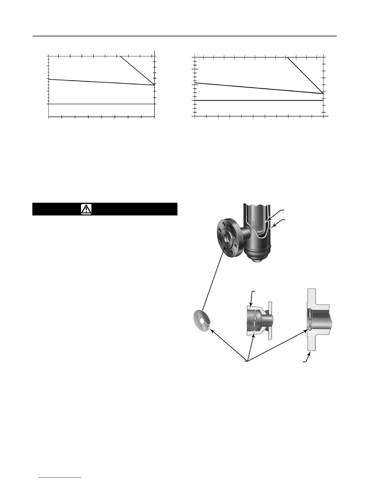
Caged sensors come with the displacer installed in the
cage. If a tubular gauge glass is ordered with the sen-
sor, the gauge glass is crated separately and must be
installed at the site. A damping plate is installed in the
lower screwed or flanged connection (see figure 3) to
provide more stable operation. Be certain that the
cage equalizing connections and the damping plate
are not plugged by foreign material.
Figure
3. Damping Plate Location
W0144–1/IL
W2141–1B/IL
DISPLACER
CAGE
SCREWED
CONNECTION
FLANGED
CONNECTION
DAMPING PLATE
 Loading...


