Type 399A-161-112
23
bly (key 7). Make sure that, if used, the diaphragm
limiter is installed beveled side up. Sparingly apply lu-
bricant to the control spring seat.
7. Install the spring case (key 2) on the body (key 1)
with the vent (key 18) oriented to allow for wrenches,
needed for connecting outlet piping, and to prevent
clogging or entrance of moisture. Install the machine
screws (key 13) and, using a crisscross pattern,
torque them to 5 to 7 foot-pounds (7 to 9 Nm)for
stainless steel constructions and 2 to 3 foot-pounds (3
to 4 Nm)for aluminum constructions.
Note
Spring case vent may be mounted in
any orientation convenient to your ap-
plication.
8. When all maintenance is complete, refer to the
Startup and Adjustment section to put the regulator
back into operation, and adjust the pressure setting.
Tighten the locknut (key 12), replace the closing cap
gasket (key 17) if necessary, and install the closing
cap (key 16).
Type 161Y or 161YM Pilot
Key numbers are referenced in figure 23 unless other-
wise noted.
Trim Parts
1. Unscrew the union ring (key 19) from the body (key
28) and remove the lower casing assembly (key 20)
and snap ring (key 17). With a Type 161Y, the lower
casing assembly (key 20) must be tipped toward the
body outlet to allow removal clearance for the pitot
tube (key 76).
2. Inspect and replace the orifice (key 27) if necessary.
Lubricate the threads of the replacement orifice and
install with 29 to 37 footpounds (39 to 50 Nm)of
torque.
3. Remove the cotter pin or groove pin (key 14) if it is
necessary to replace the disk assembly (key 25).
4. To replace or reposition the Type 161Y pitot tube
(key 76), remove the pitot tube screws (key 77), install
the pitot tube so that it points into the outlet of the
body (key 28) after the lower casing assembly (key
20) is installed, and secure with the pitot tube screws
(key 77).
5. Install the disk assembly (key 25) and secure it with
the cotter pin or groove pin (key 14).
6. If necessary, install the replacement body gasket
(key 16) into the body (key 14).
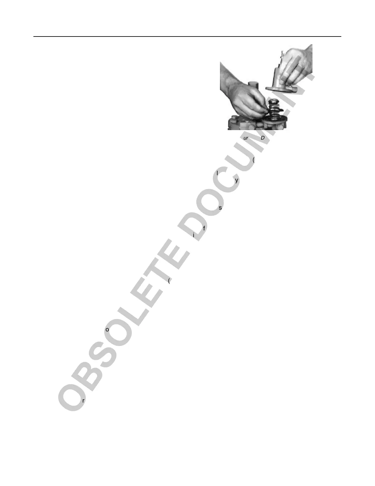
Figure 16. Diaphragm Part
Removal/Installation
W4571/IL
7. Slide the union nut (key 19) as far as it will go onto
the lower casing assembly (key 20). Install both halves
of the split ring (key 17) into the slots of the lower
casing assembly (key 20) and secure them by sliding
the union nut down on the split ring.
8. Install the lower casing assembly (key 20) with the
attached split ring (key 17) and union nut (key 19) so
that the pitot tube (key 76, if used) fits into the outlet of
the body (key 28), and the locating pin fits into one of
the four slots spaced equally around the body open-
ing.
9. Tighten the union nut (key 19) until the lower casing
assembly (key 20) is secure on the body (key 28)
Diaphragm Parts
1. Remove the closing cap (key 3) if used, and turn
the adjusting screw (key 2) counterclockwise until all
compression is removed from the control spring
(key 1).
2. Remove the hex nuts (key 22, not shown), cap
screws (key 21), spring case (key 23), and control
spring (key 1).
3. Remove the diaphragm assembly (key 5), plus at-
tached parts, by tilting them so that the relief valve
seat (key 33) slips off the lever assembly (key 9). To
separate the diaphragm or diaphragm assembly (key
5) from the attached parts, unscrew the relief valve
spring holder (key 30) from the relief valve seat (key
33).
4. Remove the diaphragm gasket (key 78) and clean
the gasket surface.
5. To replace the lever assembly (key 9), remove the
machine screws (key 11).
To replace the valve stem (key 13) or the Type 161YM
stem O-ring (key 15), also perform trim parts mainte-
nance procedure steps 1 and 3, and pull the stem (key
13) out of the lower casing assembly (key 20). With a
Type 161YM, grease the replacement stem Oring


 To Next Page