Type 399A-161-112
22
Motion Indicator Assembly
Motion indicator assembly key numbers are refer-
enced in figure 18. The indicator assembly can be re-
moved and installed without removing the bonnet (key
2) from the body (key 1).
1. Remove the indicator protector (key 22), indicator
stem guide (key 19), and indicator scale (key 21).
2. Compress the indicator spring (key 16) and remove
the indicator disk (key 20). Separate the indicator stem
(key 15), indicator spring, and stem O-ring retainer
(key 17) from the indicator stem guide (key 19).
3. Remove the indicator stem O-ring (key 18) and
check it for damage.
4. Apply lubricant to the indicator stem O-ring (key 18),
and reassemble the indicator as shown in figure 19.
5. Install the indicator assembly, indicator scale (key
21), and indicator protector (key 22) into the bonnet.
Type 161, 161M, 161EB or 161EBM Pilot
Key numbers are referenced in figure 20 unless other-
wise noted.
Trim Parts
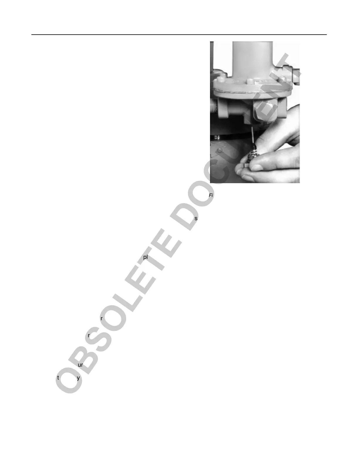
1. As shown in figure 15, remove the body plug (key 3)
to let the plug spring (key 6), and plug/stem assembly
(key 4) drop freely from the body on the Type 161 and
161EB only. On the Type 161M and 161EBM pilots
use needle nose pliers to remove the plug/stem as-
sembly.
2. Inspect the removed parts and body plug O-ring
(key 15), replace as necessary, and make sure the
plug seating surfaces are free from debris.
3. Sparingly apply lubricant or to the body plug O-ring
(key 15) and the threads of the body plug (key 3).
Install the body plug O-ring over the body plug.
4. As shown in figure 15, stack the plug spring (key 6),
and plug/stem assembly (key 4) on the body plug (key
3). Install the body plug with stacked parts into the
body (key 1).
Diaphragm Parts
1. Remove the closing cap (key 16), loosen the lock-
nut (key 12), and back out the adjusting screw (key
11) until compression is removed from the control
spring (key 9).
Figure 15. Pilot Trim Removal/Installation
W45701/IL
2. Remove the machine screws (key 13) and separate
the spring case (key 2) from the body assembly (key
1). Remove the control spring seat (key 8), the control
spring (key 9), and, if used, the diaphragm limiter (key
10).
3. Remove the diaphragm assembly (key 7) and in-
spect the diaphragm.
4. To gain access to the stem guide seal O-ring of the
Type 161M and 161EBM pilots, remove and inspect
the stem guide seal assembly (key 19), and if dam-
aged replace the complete assembly. Inspect the outer
O-ring (key 22) and replace if necessary.
5. Install the diaphragm assembly (key 7) and push
down on it to see if the plug/stem assembly (key 4)
strokes smoothly and approximately 1/16 inch (2 mm).
Note
In step 6, if installing a control spring of
a different range from the one that was
removed, be sure to delete the spring
range originally appearing on the spring
case and indicate the new spring range.
A diaphragm limiter (key 10), as well as
other parts given in the Type 161 or
161M Pilot parts list section, is required
with the highest-range spring.
6. As shown in figure 16, stack the control spring (key
9), the control spring seat (key 8), and, if used, the
diaphragm limiter (key 10) onto the diaphragm assem-


 To Next Page