Type 399A-161-112
25
Note
In step 6, if installing a control spring of
a different range from the one that was
removed, be sure to delete the spring
range originally appearing on the spring
case and indicate the new spring range.
6. As shown in figure 16, stack the control spring (key
9), the control spring seat (key 8) and the diaphragm
limiter (key 10) onto the diaphragm assembly (key 7).
Make sure that the diaphragm limiter is installed as
shown in figure 21. Sparingly apply lubricant to the
control spring seat.
7. Install the spring case (key 2) on the body (key 1)
with the vent (key 18) oriented to allow for wrenches,
needed for connecting outlet piping, and to prevent
clogging or entrance of moisture. Install the machine
screws (key 13) and, using a crisscross pattern,
torque them to 5 to 7 foot-pounds (7 to 9 Nm)for
stainless steel constructions and 2 to 3 foot-pounds (3
to 4 Nm)for aluminum constructions.
Note
Spring case vent may be mounted in
any orientation convenient to your ap-
plication.
8. When all maintenance is complete, refer to the
Startup and Adjustment section to put the regulator
back into operation, and adjust the pressure setting.
Tighten the locknut (key 12), replace the closing cap
gasket (key 17) if necessary, and install the closing
cap (key 16).
Type 112 Restrictor
Perform this procedure if replacing any of the groove
valve O-rings or other parts. Key numbers are refer-
enced in figure 19 unless otherwise noted.
1. Unscrew the groove valve (key 22) and retainer
(key 23) just enough to loosen them, but do not com-
pletely separate.
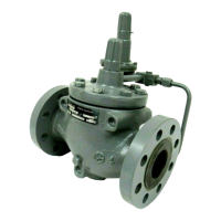
2. As shown in figure 17, push on the retainer (key 23)
to push the groove valve (key 22) out of the body (key
21). Then complete disassembly.
3. Replace the groove valve O-rings (key 24) if neces-
sary, being sure to apply lubricant to the replacement
O-rings before installing them in the groove valve and
retainer.
4. Install the groove valve (key 22) into the same side
of the body where the scale appears. Install the retain-
er into the opposite side of the body, and tighten until
both are secure.
Figure 17. Pushing Groove Valve
Up with Retainer
W4573/IL
5. When all maintenance is complete, refer to the
Startup and Adjustment section to put the regulator
back into operation.
ParPartsts OrOrderingdering
When corresponding with your Fisher sales office or
sales representative about this equipment, always ref-
erence the equipment serial number or FS number
that can be found on a nameplate attached to the bon-
net (key 2, figure 18).
When ordering replacement parts, reference the key
number of each needed part as found in the following
parts reference.
ParPartsts ListList
Type 399A Main Valve (figure 18)
Key Description Part Number
Parts Kit (included are a cage removel tool,
keys 5, 6, 8, 9, 14, 18,
and also includes keys 66 and 67 used
with size 8 x 6 only)
E55 diaphragm material, 0 to 150
d
F
(18 to 66
d
C) temperatures
For 1-inch body R399AX00S12
For 1-1/4 x 1, 1-1/2 x 1 and
2 x 1-inch body R399AX00S72
For 2 or 4 x 2-inch body R399AX00S22
For 3-inch body R399AX00S32
For 4, 6 x 4, or
8 x 4-inch body R399AX00S42
For 6, 8 x6 or 12 x 6-inch body R399AX00S62
E54 diaphragm material, 20 to 150
d
F
(29 to 66
d
C) temperatures
For 1-inch body R399AX00L12
For 2 or 4 x 2-inch body R399AX00L22
For 3-inch body R399AX00L32
For 4, 6 x 4 or
For 8 x 4-inch body R399AX00L42
For 6, 8 x 6 or 12 x 6-inch body R399AX00L62
1 Valve Body
If you need a valve body as a replacement part,
order by body size, serial number, and desired material.
2 Bonnet
For 1-inch body, WCB steel 30B7997X012
For 11/4 x 1-inch body 30B7997X012
For 1-1/2 x 1 body 34B8673X012
 Loading...


