The document is an owner's manual for the FISHER 95331 Low-Profile Tailgate Spreader, Model 500. It provides comprehensive information regarding the spreader's installation, operation, maintenance, and safety guidelines. This manual is specifically for FISHER Model 500 Low-Profile Tailgate Spreaders with serial numbers beginning with 030101 and higher, and it supersedes all earlier editions.
Function Description
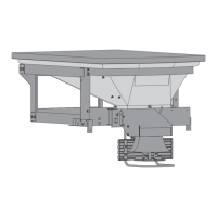
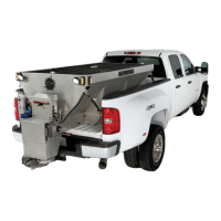
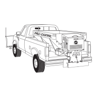
The FISHER 95331 Low-Profile Tailgate Spreader, Model 500, is designed for spreading snow and ice control materials. It is intended for use with vehicles and is mounted to a receiver hitch. The spreader features a hopper for material storage and a spinner mechanism to distribute the material. The control system allows for variable speed operation or ON/OFF control, depending on the model style.
Important Technical Specifications
- Model: 500 Low-Profile Tailgate Spreader
- Serial Numbers: 030101 and higher
- Material Capacity (Approximate Total Weight):
- 5.0 ft³: 480 lb (400 lb material + 80 lb base)
- 3.5 ft³: 360 lb (280 lb material + 80 lb base)
- 1.5 ft³: 200 lb (120 lb material + 80 lb base)
- Material Density (Approximate):
- Salt: 80 lb/ft³ (2160 lb/yd³, 1282 kg/m³)
- Sand: 100 lb/ft³ (2700 lb/yd³, 1602 kg/m³)
- Motor Specification: 12V DC, 0.56 kW Motor
- Fuses:
- 6A Fuse (Two-Way Molded Connector)
- 30A Fuse (Battery connection)
- 10A Fuse (3-pin harness, for older controls)
- Wiring Harness: 4-pin harness
- Noise Emission: Below 70 dB(A) for the spreader operator
- Certifications: Conforms to EU Machinery Directive 2006/42/EC and Directive 2011/65/EC (RoHS2).
Usage Features
The spreader offers two main control options: Variable Speed (PWM) Control (new and old styles) and ON/OFF Control.
Variable Speed (PWM) Control – New Style:
- START/BLAST Button: Starts the motor and allows for a temporary "BLAST" or maximum speed operation when held down. Releasing the button returns to the preset speed.
- OFF Button: Stops the motor and functions as an emergency stop.
- Speed Dial: Adjusts the spinner speed. Turning clockwise increases speed (indicated by green LEDs), and counterclockwise decreases speed.
- Diagnostic Indicator Light: Flashes a specific number of times to indicate problems (e.g., no fault, no power, no motor, no ground, overheated, excess current).
- Ignition Requirement: The truck ignition must be ON to start the spreader. If the truck ignition is turned OFF while running, the motor will stop.
Variable Speed (PWM) Control – Old Style:
- Power Switch (START/BLAST, ON, OFF):
- "START/BLAST" position (momentary): Starts the motor or provides maximum speed when held. Returns to "ON" when released.
- "ON" position: Spreader operates at the speed selected on the speed dial.
- "OFF" position: Stops the motor and functions as an emergency stop.
- Speed Dial: Adjusts the spinner speed. Turning clockwise increases speed, and counterclockwise decreases speed.
- Spinner Indicator Lights: Two lights (red for fault, green for power ON/motor running) indicate motor status.
- Ignition Requirement: The truck ignition must be ON to start the spreader. If the truck ignition is turned OFF while running, the motor will stop.
ON/OFF Control:
- Power Switch (ON, OFF, BLAST):
- "ON" position: Starts the motor immediately.
- "OFF" position: Stops the motor and functions as an emergency stop.
- "BLAST" position (momentary): Provides maximum speed when held. Returns to "OFF" and stops the motor when released.
- Spinner Indicator Light: An illuminated light indicates power to the motor.
- Ignition Requirement: The truck ignition must be ON to start the spreader. If the truck ignition is turned OFF while running, the motor will stop.
General Usage:
- Loading: Only dry, clean, free-flowing snow and ice control materials should be used. Wet materials or materials with foreign debris are not recommended. Overloading beyond GVWR or GAWR ratings is prohibited.
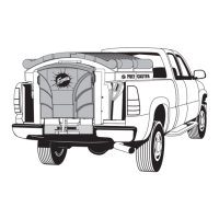
- Driving and Spreading: Emphasizes defensive driving, maintaining good visibility, slowing down, and avoiding distractions. Recommends an OSHA compliant backup alarm for governed employers due to reduced rear visibility.
- Spinner Ring Kit (PN 95475): Recommended for spreading materials with grain size smaller than 1/16" to prevent "free flowing" when the spreader is OFF.
Maintenance Features
The manual outlines detailed preseason, postseason, and general maintenance procedures.
General Maintenance:
- Cleaning: Thoroughly clean the spreader inside and out after every use, disconnecting electrical power first. Tap water or a high-pressure washer can be used.
- Material Handling: DO NOT leave unused material in the hopper, as it can freeze or solidify. Empty and clean after each use.
- Lubrication: Lubricate grease fittings after each use with a good quality multipurpose grease.
Preseason Check:
- Drive Belt: Inspect for cracks or damaged teeth; replace if needed.
- Motor Connection Terminals: Check for damage or corrosion; clean, replace, and coat with dielectric grease if necessary.
- Drive Shaft Bearings: Remove the drive belt, spin the shaft by hand, and check for noise or roughness. Grease thoroughly with low-temperature synthetic grease if they pass inspection.
- Drive Sprocket Set Screws: Verify tightness.
- Motor Cap Assembly Seal: Check condition and replace if needed.
- Spinner Disk: Inspect for excessive wear; replace if necessary.
- Fasteners: Tighten all fasteners according to the Torque Chart.
- Vehicle Stoplights: Verify visibility and proper function.
Postseason Maintenance:
- Cleaning: Thoroughly clean the unit inside and out.
- Electrical Connections: Apply dielectric grease to all electrical connections to prevent corrosion.
- Bearings: Grease the drive shaft bearings.
- Metal Surfaces: Oil or paint all bare metal surfaces.
- Storage: Place the lid on the hopper body and secure the latch. Store the unit upright, stabilized with supports, and on blocks if outdoors to eliminate ground moisture.
Drive Belt Replacement:
- Remove the motor cap assembly.
- Loosen four Phillips head screws fastening the motor mount.
- Slide the motor toward the drive shaft.
- Remove and replace the belt.
- Slide the motor mount away from the drive shaft until the belt deflects approximately 3/8" when proper tension is achieved.
- Tighten the four Phillips head screws and replace the motor cap.
- Caution: Overtightening the belt can damage the motor or bearings.
Bearing and Set Screw Maintenance:
- Set Screws: Tighten all set screws (motor pulley, shaft pulley, auger, bottom bearing) after every 60 hours of use.
- Top Bearing: Grease after every 60 hours of use with a good quality multipurpose grease.
- Bottom Bearing: Grease after every 8 hours of use with a good quality multipurpose grease, due to the harsh environment.
Recycling:
- At the end of its useful life, the majority of components (steel) can be recycled. Gear oil must be disposed of according to local regulations. Plastic parts should be disposed of in a customary manner.