Instruction Manual
D103198X012
i2P-100 Transducer
July 2014
24
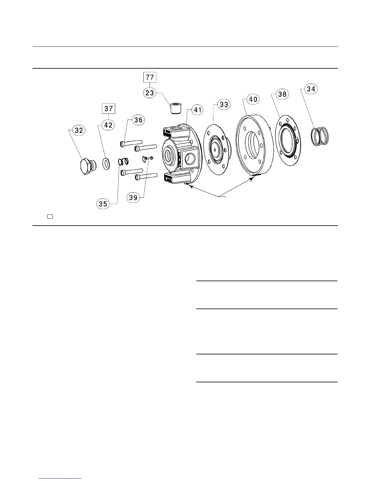
Figure 14. Fisher i2P‐100 Relay Assembly
30C2258‐B
NOTE:
APPLY LUBRICANT/SEALANT/ADHESIVE
TABS ON BODY BLOCK AND RELAY BODY MUST ALIGN
WITH TAB ON THE TRANSDUCER HOUSING ASSEMBLY
Key Description Part Number
PWB/Cup Assembly
24 PWB/Cup Assembly
97 Machine Screw (2 req'd)
98 Machine Screw
Relay Assembly (see figure 14)
41 Relay / Body Assembly
42* O‐Ring 1E5477X0062
36 Machine Screw, fill hd (4 req'd)
32 Body Plug
33 Exhaust Port Assembly
34 Spring
35 Spring
37 Lubricant, silicone sealant (not furnished with relay)
38* Upper Diaphragm 21B2362X012
39* Valve Plug 21B2370X012
40 Body Block
77 Anti‐Seize Sealant (not furnished with relay)
I/P Converter Assembly
43 I/P Converter Assembly
Gauge/Pipe Plug
23 Pipe plug, use when gauge is not specified (not shown)
Alloy steel pl
Stainless steel
23* Gauge, (not shown)
0-30 psig/0-0.2 MPa/0-2 bar 11B8579X022
0-60 psig/0-0.4 MPa/0-4 bar 11B8579X032
Key Description
Diagnostic Connections
Note
Part numbers are shown for recommended spares only. For part
numbers not shown, contact your Emerson Process Management sales
office.
FlowScannert diagnostic system hook‐up
Includes pipe tee, pipe nipple, pipe bushings, connector body,
and body protector. See figure 7 for part identification.
Note
If the i2P‐100 transducer is used in a valve assembly with a positioner, no
hook‐up for diagnostic testing is required for the i2P‐100. The hook‐up
for diagnostic testing should be installed at the positioner.
Side Output
For units with gauges
SST fittings
Brass fittings
For units without gauges
SST fittings
Brass fittings
*Recommended spare parts

 Loading...