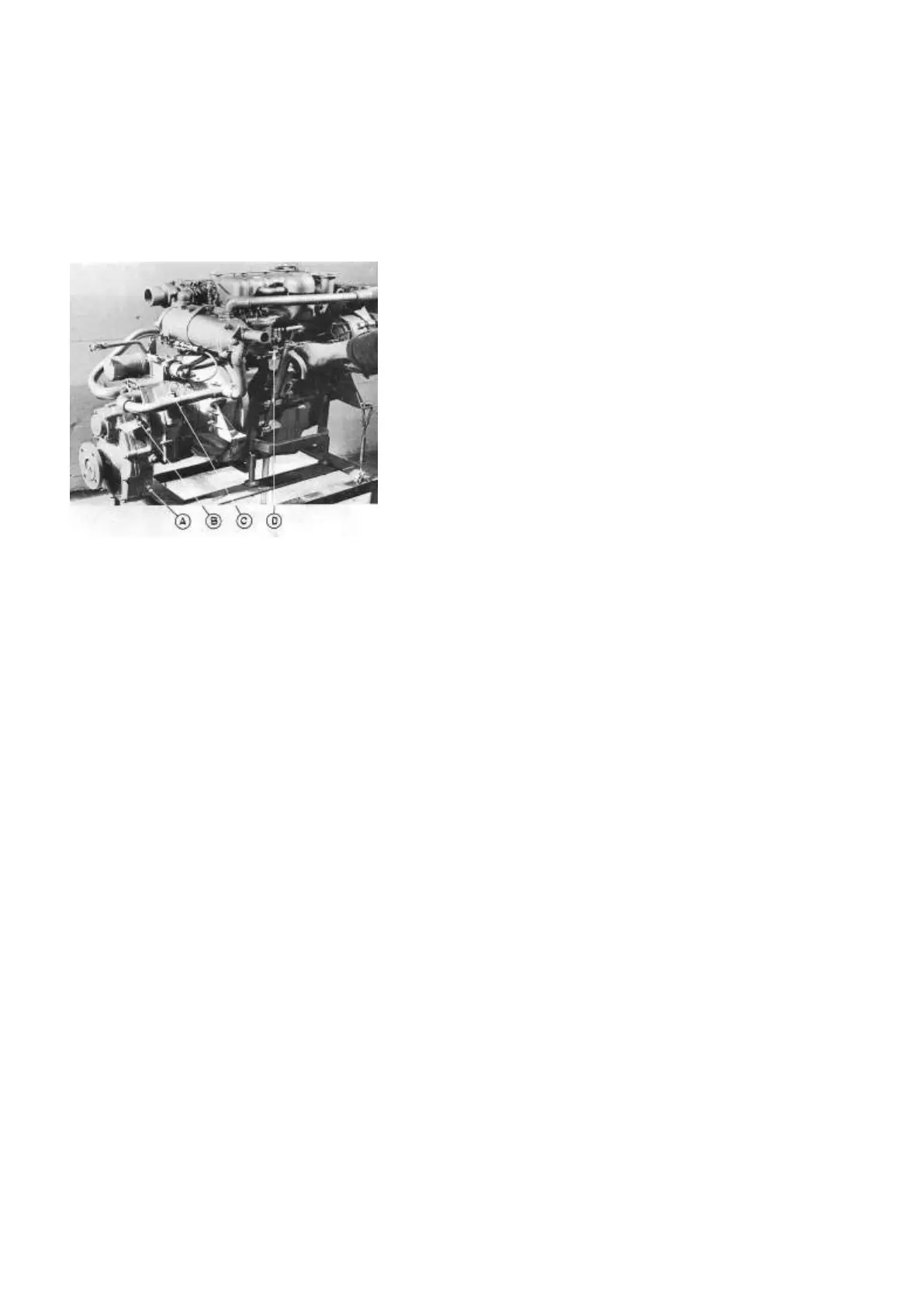
Plate 26
Engine - Starboard Side View
A) Reduction Gear Oil Level Plug
B) Reduction Gear Oil Filler Plug
C) Reverse Gear Oil Dip Stick and Filler Cap
D) Manual Fuel Feed Pump Level
e) Bleeding the fuel system
Avoid running out of fuel! If - on a diesel engine -
air is trapped in the fuel line, the engine refuses to
work. This is a consequence of the fuel injection
system. If, however, air has been enclosed in the
fuel line, either as a result of running out of fuel or
after any part of the system between the
fuel tank and the fuel injection pump has been
disconnected, the fuel system will have to be bled.
Usually the fuel system on the PERKINS 4.108 V
(and 4.107) is very easily bled (see plate 25 and 26).
Slacken the vent valve fitted on the hydraulic head
looking screw on the injection pump on the port side
of the engine (plate 25). Then operate the lever on
the fuel pump fitted on the engine’s starboard side
(plate 26) until fuel, free from air bubbles and foam,
issues from the venting screw.
(If it is not possible to move the feed pump lever, the
camshaft driving the lift pump lever may be on
maximum lift. If so, turn the engine one revolution
by using the electric starter momentarily.)
Then tighten the venting screw, and the engine
is ready for starting. Disengage the gear control
(see paragraph 3.6), push the speed control lever to
maximum speed position, and engage the starter by
turning the starting key.
If the engine does not start at this occasion, a more
comprehensive bleeding procedure has to be carried
out, as described in the “Handbook for the Perkins
Marine Diesel Engines” (delivered together with the
MANUAL) in the chapter “Bleeding the Fuel
System.”
f) Periodic attentions
The (enclosed) “Handbook for the Perkins Marine
Diesel Engines” specifies the periodic checks for the
maintenance of the engines. The handbook indicates
that, besides frequent checking of engine sump oil
level as described in paragraph 3.7 of this manual, the
coolant level and gearbox oil level should also be
checked daily if the engine is running continuously.
The filler cap for the engine coolant is visible on plate
22. To open: Push down and turn counter-clockwise.
Be careful if the cap has to be opened
when the engine is warm or hot, as the cooling system
is then under pressure. Turn the cap slowly: The level
of the coolant should be just a little below the neck of
the filler pipe.
The TMP gear box with reduction gear is divided into
two compartments: the forward one containing the
reversing gear, and the aft compartment housing the
reduction gear. The oil level on the
reversing gear box is checked by means of the dip
stick on the starboard side of the casing, while the oil
level on the reduction gear box is checked by means of
the oil level plug low down on the casing, on the
starboard side. The oil filler cap for the revers-