Plate 30
Fresh Water Pressure Pump Unit
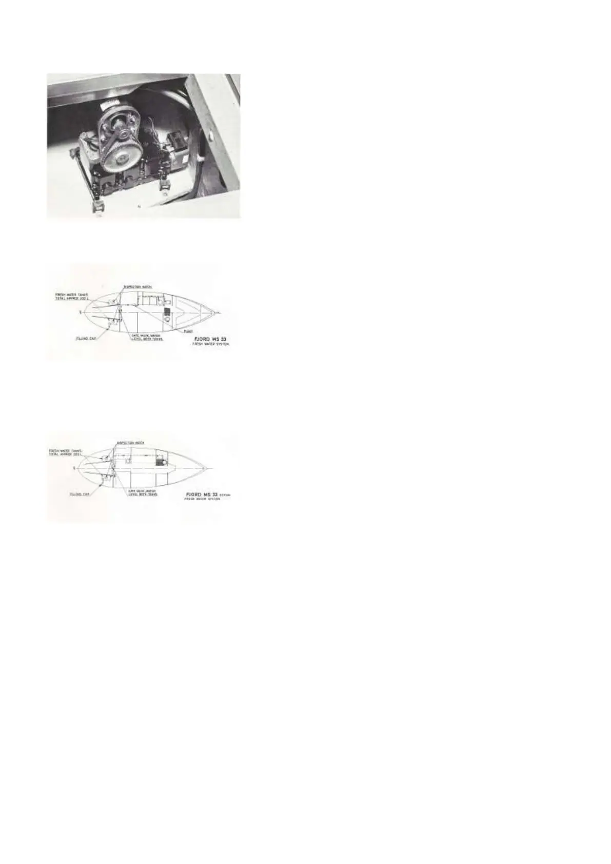
Diagram 2 A
Fresh Water System - Version A
Diagram 2 B
Fresh Water System - Version B
carried out every 150 hours (3 months) of engine
operation. Brittle hoses must be replaced.
Although space is restricted, the diaphragm
pump fitted in the cockpit coaming should be
disconnected for inspection (plate 29).
d) Fresh water and sanitary system
Two fresh water tanks are fitted, located on each side
of the cockpit, below the bottom-plates in the stowing
ompartment below cockpit seats. Just abaft the aft
engine room bulkhead. (In boats built before 1973, a
single fresh water tank is fitted below the cabin sole.)
The fresh water tanks are connected with a “T”-joint
before the hose-line is led to the manual pumps in
Version A and to the water pressure pump system of
Version B. Diagrams 2 A and B show the systems
fitted in Version A and Version B respectively.
Only one filler cap is provided for the two fresh water
tanks. The cap is fitted in the side deck to starboard,
just adjacent to the cockpit. The word WATER is
engraved on the fitting itself, and the filler pipe for
water MUST NOT BE MIS-
TAKEN FOR THE FUEL FILLER PIPE fitted farther
forward to PORT.
When topping up the water tanks, the gate valve fitted
to the hose connecting the two tanks must be opened
to let water from the starboard flow across and into the
port tank. This gate valve is accessible through the
opening in the bulkhead
behind the ladder leading from the cockpit to the dog-
house, where the wheel of the valve protrudes through
the bottom plate of the stowing compartment close to
the bulkhead. Usually this valve is fitted to port, but on
some of the Version A-boats, you will find this valve
to starboard in the stowing compartment. Whenever
you are sailing in heavy
weather, with large angles of heel, see that this gate
valve is closed to avoid water flowing from the wind-
ward tank high up and down to the leeward tank,
with valuable fresh water being lost through the
leeward tank’s ventilating pipe as result.
The fresh water tanks are Ventilated to the hollow
cockpit coamings (forward end each side) to avoid
salt water entering when spray is flying in rough
weather.
An inspection hatch is provided on top of each of
the fresh water tanks, and these hatches have to
be removed for cleaning the tanks.
As mentioned in paragraph 4.2 a, since the fresh
water tanks as well as the fuel tank are welded of
heavy gauge, sea-water resistant, aluminium alloy,
the tank plating should be kept as clean as possible to
avoid any galvanic effects and corrosion of
the alloy.