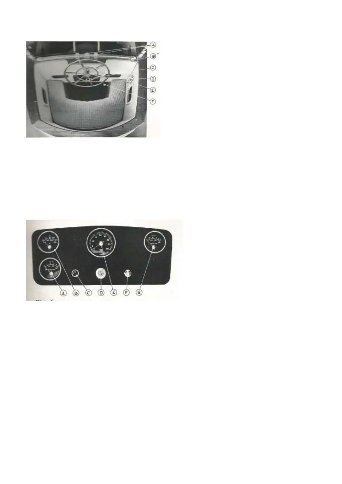
Plate 5
Steering Position in Cockpit — Version A
A) Main Sheet Traveller and Adjustable End stops
B) Steering Wheel with Shaft Brake
C) Instrument Panel (Engine Instruments)
D) Engine Stop Control
E) Propeller Stop Control
F) Engine Throttle and Gear Control
Plate 6
Version A — Instrument Panel
A) Oil Pressure gauge - Engine Lubricating Oil
B) Coolant Temperature Gauge ’
C) Control Light — Charging
D) Starting Switch/Key
E) Tachometer
F) Switch — Instrument Panel Light
G) Oil Pressure Gauge — Gear Box
6) Steering positions instrumentation
Version A
Version A is, as standard, fitted with outside steering
position only (plate 5 and 6). The plates clearly show
the location of instruments and controls.
Dials are fitted for showing oil pressure on the gear
box and in the engine lubricating system respectively.
The pointers should not be allowed to drop below 85
lbs/sq.in. (60 kg/cm2) and below 30 lbs/sq.in. (2,1
kg/cm2) for the gearbox and engine oil respectively,
with the engine running at 3000 rpm.
In the cockpit coaming to starboard are fitted the push-
pull controls for the propeller locking device and the
engine stop .The upper one operates the engine stop,
and is to be pulled out to stop the engine. See that the
lever is pushed back to its inner position before you try
starting the engine again! The lower lever is for the
propeller lock, and this lever MUST be pulled out
before starting the engine and engaging the gear box.