3) Electrical systems
a) General
12 Volt current is provided throughout. Although
only one high capacity alternator fitted on the
engine is used for charging the batteries, the
electrical system is divided into two separate
circuits, in that the alternator is charging through
double diodes. The double diodes act just
as one-way valves: they let current pass from
the alternator to both batteries simultaneously, but
they do NOT let any current pass in the
opposite direction - from the one battery circuit
to the other. Thus, without having to operate any
complicated system of switches, you are always
sure that no current is taken from the starting
battery as long as you are not turning the starting
key, and unless the emergency switch is switched
on (see paragraph 3.3). Consequently, your
starting battery will always be fresh, and thanks to
the automatically functioning diodes you never have
to fear finding yourself with flat starting batteries
after happy days aboard without engine noise'.
The operating of the electrical systems is described
in the paragraphs 3.3, 3.4 and 3.5.
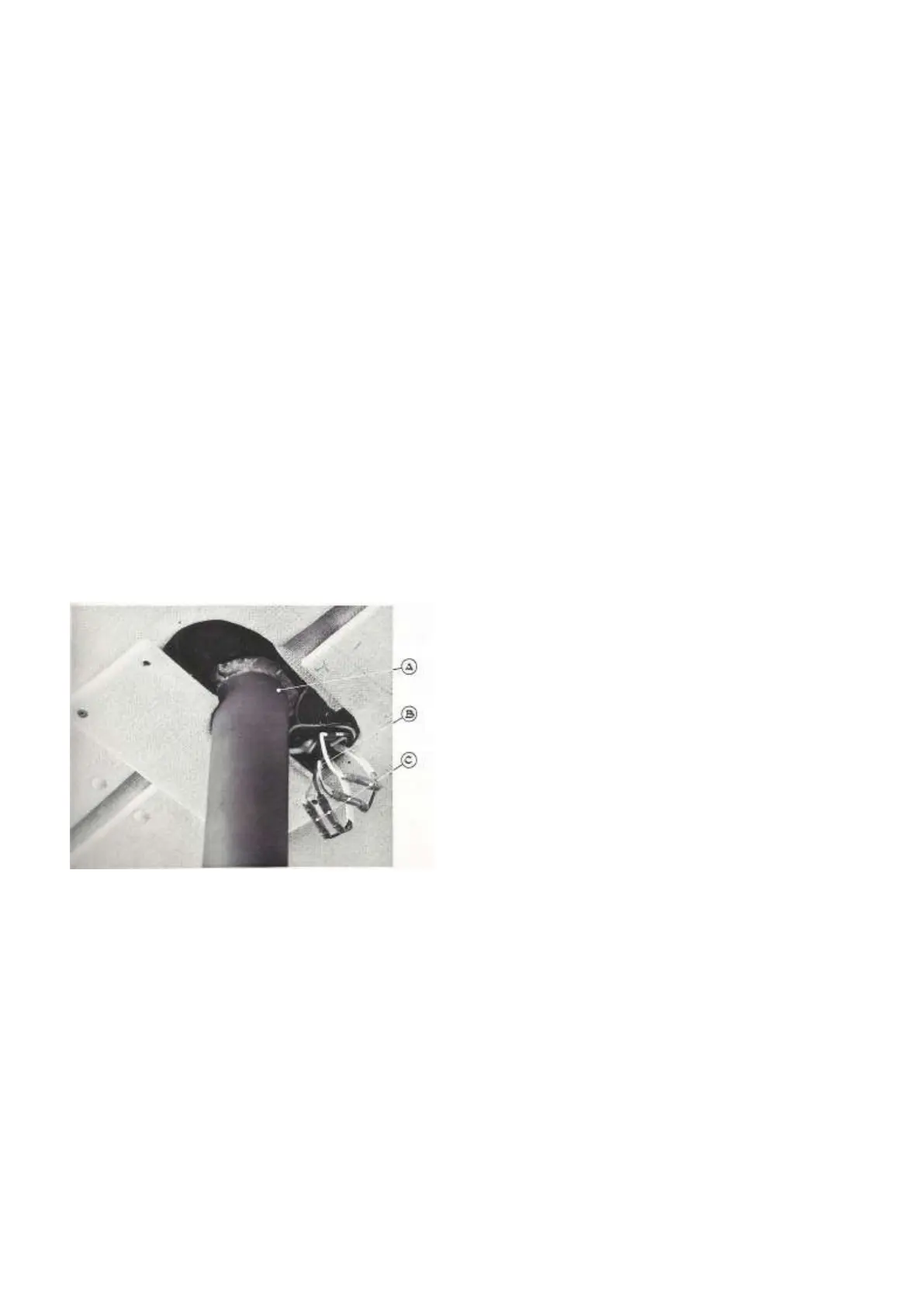
Plate 33
Wiring Connections - Mast Harness
A) Mast Pillar flanged to Coach Roof
B) Mast Harness - Wiring for Top Light and Deck
Flood Light
C) Connections
b) The batteries
The batteries are fitted below the dog-house sole,
and they are accessible through the two hatches
on each side of the engine compartment. The star-
ting battery is fitted to starboard, and the battery
for ship’s service is fitted to port. Both batteries
have a capacity of 90 Ah.
The liquid level in the batteries should be checked
each time the boat is fuelled, and at least once a
month. If necessary, distilled water should be added
until the lead plates are completely covered.
If the batteries require addition of water at frequent
intervals, this may imply that the batteries are being
overcharged. The regulator on the alternator should
then be properly checked for function.
During each of the periodical services to be carried
out every 150 hours (or 3 months) of engine operation,
the batteries should be thoroughly inspected: The
battery posts and cable clamps should be cleaned with
a wire brush and all exposed metal parts of the battery
cable clamps and battery terminals should be given a
light coating of oil, grease or acid-free Vaseline. No
oil should be spilled, however, as this might harm the
battery case.) '
The batteries should be inspected for leakages,
and all terminals, including the batteries themselves,
should be checked that they are properly secured.
c) Wiring diagram
A complete wiring diagram including both electrical
systems is shown in Diagram 4 A and 4 B for
Version A and Version B respectively. All items are
clearly described in English.
It most be noted that the connections for top light,
deck flood light and (Optional) anchor light are
located inside the coach roof covering, accessible
through the small hatch in the ceiling just where
the mast pillar emerges (plate 33). The wiring for
the circuits mentioned above MUST be disconnected
if the mast is to be unstepped.
d) Periodical maintenance
Generally speaking, the electrical systems are free
from maintenance except for the cases already
mentioned (paragraph 4.3.b). Nevertheless the
following notes should be observed:
Damp air and moisture are the main causes of any
trouble with the electrical systems. It is therefore
important that all instrument panels, all connections,
etc. are kept as dry and clean from dirt as
possible. Not only does this concern the decorative