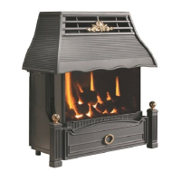
2.8 REMOVING / RE-FITTING THE GLASS FRAME ASSEMBLY
a) The glass frame is held in position by hooking the top flange over the
combustion chamber opening at the top as shown in Fig. 10 below.
Fig. 10
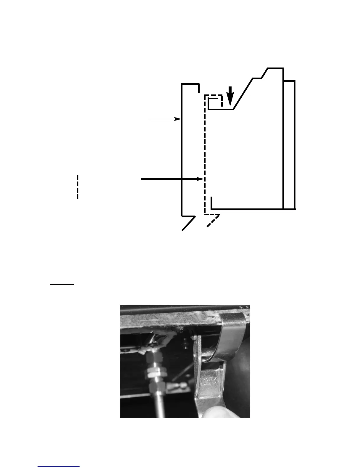
b) The assembly is then secured to the bottom of the combustion chamber
by the two hinge clamp brackets as shown below in Fig. 11. These are
clamped together to form the seal between the glass frame assembly
and the combustion chamber.
NOTE :
Always ensure that a consistent seal between the combustion
chamber and the glass frame is achieved.
Fig. 11
13
Glass Frame Assembly
l
ocates over lip on top of
combustion chamber lid, and
drops onto flange as shown.
To remove, unclip base clips
as shown in Fig. 11 and lift
clear.
denotes correct
final position of
glass frame.
Combustion
Chamber
 Loading...