Printed in U.S.A.
Page 4
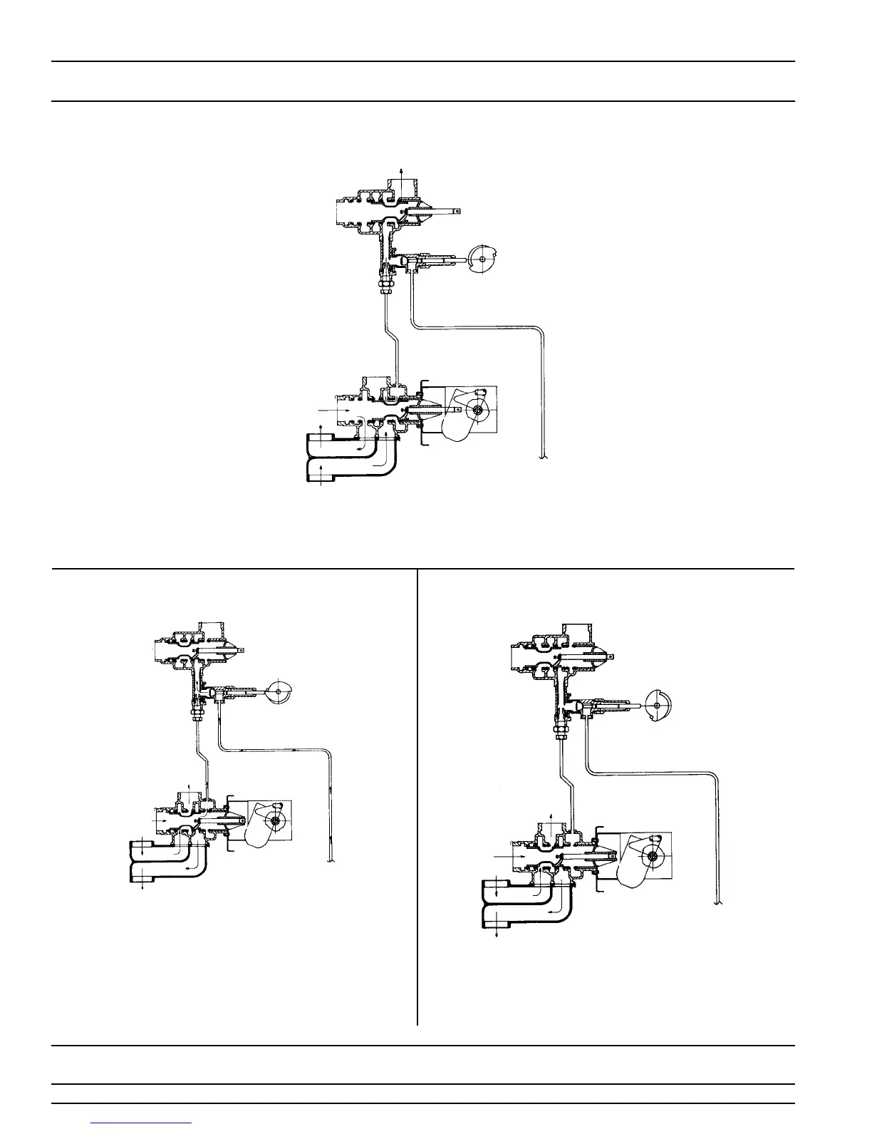
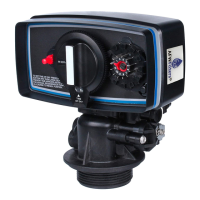
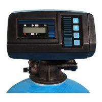
MODEL 3150 UP-FLOW
Water Conditioner Flow Diagrams
1 SERVICE POSITION
Hard water enters at valve inlet flows thru valve to the top of tank down thru mineral to the
bottom distributor. Conditioned water flows to the valve, around the piston and out the outlet.
2 BRINE AND SLOW RINSE POSITION
3 BACKWASH POSITION
Hard water enters at valve inlet flows thru the piston to the
injector nozzle and throat to draw brine from the brine tank
brine flows thru valve to the bottom of tank up thru
mineral to top of tank, around the piston and out the drain.
Flow thru injectors continues for slow rinse for remainder of
cycle. Hard water is also available at valve outlet
.
Hard water enters at valve inlet flows thru piston to the
bottom of tank up thru mineral to top of tank, around the
piston and out the drain. Hard water is also available at valve
outlet.
OUTLET
INLET
DRAIN
TO BRINE
INLET
TOP OF TANK
BOTTOM OF
TANK
OUTLET
INLET
DRAIN
TO BRINE
TANK
INLET
TOP OF TANK
BOTTOM OF
TANK
OUTLET
TO BRINE
TANK
BOTTOM
OF TANK
TOP OF TANK
INLET
DRAIN
INLET
TANK