Printed in U.S.A.
Page 26
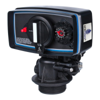
MODEL 5600SE Upflow
Service Instructions
A. TO REPLACE TIME BRINE VALVE, INJECTORS,
AND SCREEN
1. Turn off water supply to conditioner:
a. If the conditioner installation has a three valve by-
pass system, first open the valve in the by-pass
line, then close the valves at the conditioner inlet
and outlet.
b. If the conditioner has an integral by-pass valve,
put it in the by-pass position.
c. If there is only a shut-off valve near the
conditioner inlet, close it.
2. Relieve water pressure in the conditioner by stepping
the control into the backwash position momentarily.
Return the control to the service position.
3. Unplug electrical cord from outlet.
4. Disconnect brine tube and drain line connections at
the injector body.
5. Remove the two injector body mounting screws. The
injector and brine module can now be removed from
the control valve. Remove and discard brine body O-
rings.
6A. To replace brine valve.
1. Pull brine valve from injector body, also remove
and discard O-ring at bottom of brine valve hole.
2. Apply silicone lubricant to new O-ring and
reinstall at bottom of brine valve hole.
3. Apply silicone lubricant to O-ring on new valve
assembly and press into brine valve hole,
shoulder on bushing should be flush with injector
body.
6B. To replace injectors and screen.
1. Remove injector cap and screen, discard O-ring.
Unscrew injector nozzle and throat from injector
body.
2. Screw in new injector throat and nozzle, be sure
they are sealed tightly. Install a new screen.
3. Apply silicone lubricant to new O-ring and install
around oval extension on injector cap.
7. Apply silicone lubricant to three new O-rings and
install over three bosses on injector body.
8. Insert screws with washers thru injector cap and
injector. Place this assembly thru hole in timer
housing and into mating holes in the valve body.
Tighten screws.
9. Disconnect brine tube and drain line.
10. Return by-pass or inlet valving to normal service
position. Water pressure should now be applied to the
conditioner, and any by-pass line shut off.
11. Check for leaks at all seal areas. Check drain seal
with the control in the backwash position.
12. Plug electrical cord into outlet.
13. Set time of day and cycle the control valve manually
to assure proper function. Make sure control valve is
returned to the service position.
14. Take sure there is enough salt in the brine tank.
15. Start regeneration cycle manually if water is hard.
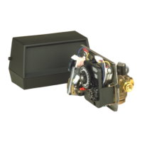
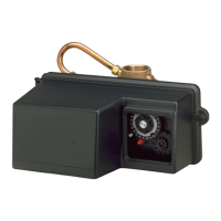
B. TO REPLACE TIMER
1. Follow Steps A.1 through A.3 .
2. Remove the control valve back cover. Remove
the control valve front cover. Disconnect the
meter dome signal wire from the front cover and
feed it back through the control.
3. Remove screw and washer at drive yoke.
Remove timer mounting screws. The entire timer
assembly will now lift off easily.
4. Put new timer on top of valve. Be sure drive pin
on main gear engages slot in drive yoke.
5. Replace timer mounting screws. Replace screw
and washer at drive yoke. Replace meter signal
wire.
6. Return by-pass or inlet valving to normal service
position. Water pressure should now be applied
to the conditioner, and any by-pass line shut off.
7. Replace the control valve back cover.
8. Follow Steps A.12 through A.15 .
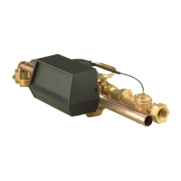
C. TO REPLACE PISTON ASSEMBLY
1. Follow Steps A.1 through A.3 .
2. Remove the control valve back cover. Remove
the control valve front cover. Disconnect the
meter dome signal wire from the front cover and
feed it back through the control.
3. Remove screw and washer at drive yoke.
Remove timer mounting screws. The entire timer
assembly will now lift off easily. Remove end plug
retainer plate.
4. Pull upward on end of piston yoke until assembly
is out of valve.
5. Inspect the inside of the valve to make sure that
all spacers and seals are in place, and that there
is no foreign matter that would interfere with the
valve operation.
6. Take new piston assembly as furnished and push
piston into valve by means of the end plug. Twist
yoke carefully in a clockwise direction to properly
align it with drive gear. Replace end plug retainer
plate.