PAGE 10 QualityWaterForLess.com Help: 888-426-5001
sta n dar d
fIne MesH
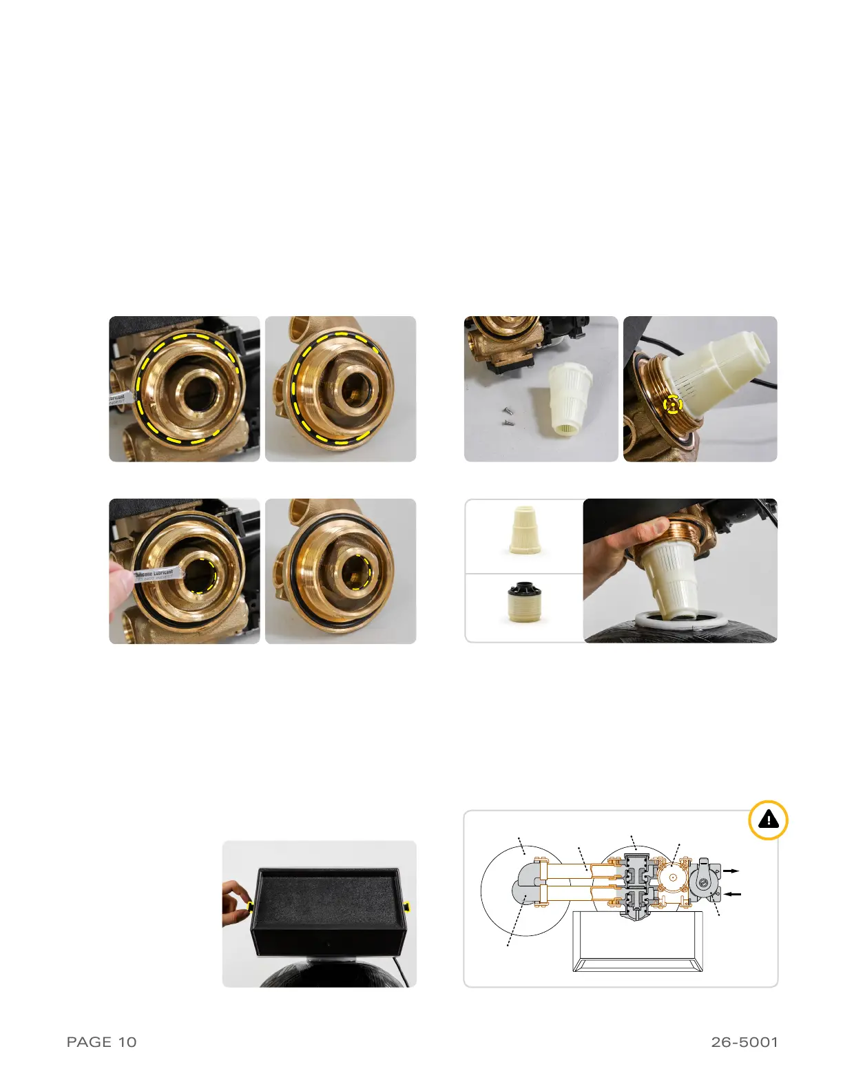
3 ›InstallInG tHe flecK 9000 ValVe
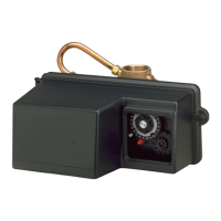
1) Remove the filling funnel and tape and while
using the included silicone lubricant packet, lu-
bricate the inner and outer o-rings on the bottom
of the Fleck 9000 Meter Valve and the second
tank adapter as shown in Figures 10-A and 10-B
2) Loosely fit a
top screen/upper distributor (stan-
dard OR fine mesh)
to the bottom of the Fleck
9000 Meter Valve and the second tank adapter,
make a mark through both of the screen screw
holes on both screens, drill two 3/32” holes on both
top screens at those marks, and screw into place
(Figure 10-C). Then place the valve onto the top of
the tank with the riser tube fitting into the central
o-ring on the valve (Figure 10-D).
Hand-tighten
the
valve to the tank.
Do not use Teflon tape or pipe
dope on the valve or tank threading
adaPter . fIGure 10-aValVe fIGure 10-c
adaPter . fIGure 10-bVa lV e
fIGure 10-d
fIGure 10-e systeM toP VIew . fIGure 10-f
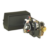
3) Loosen the two valve case screws to uncover the
front of the valve to prepare for the next step of
removing the plumbing adapter clips (Figure 10-E)
4) Please review the diagram below to make sure
you install the meter, bypass, and tube assembly
on the correct side of the valve (Figure 10-F).
i
Please note that you absolutely must not
attach these components on the wrong side
of the valve
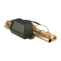
Tank 1
Tank 2
Tube Assembly
Water Meter
Outlet
Inlet
Bypass Valve
Main Control Valve
Tank 2 Adapter
 Loading...