7 Connection FLUXUS F70x
UMFLUXUS_F7V4-6-2EN, 2017-10-01 67
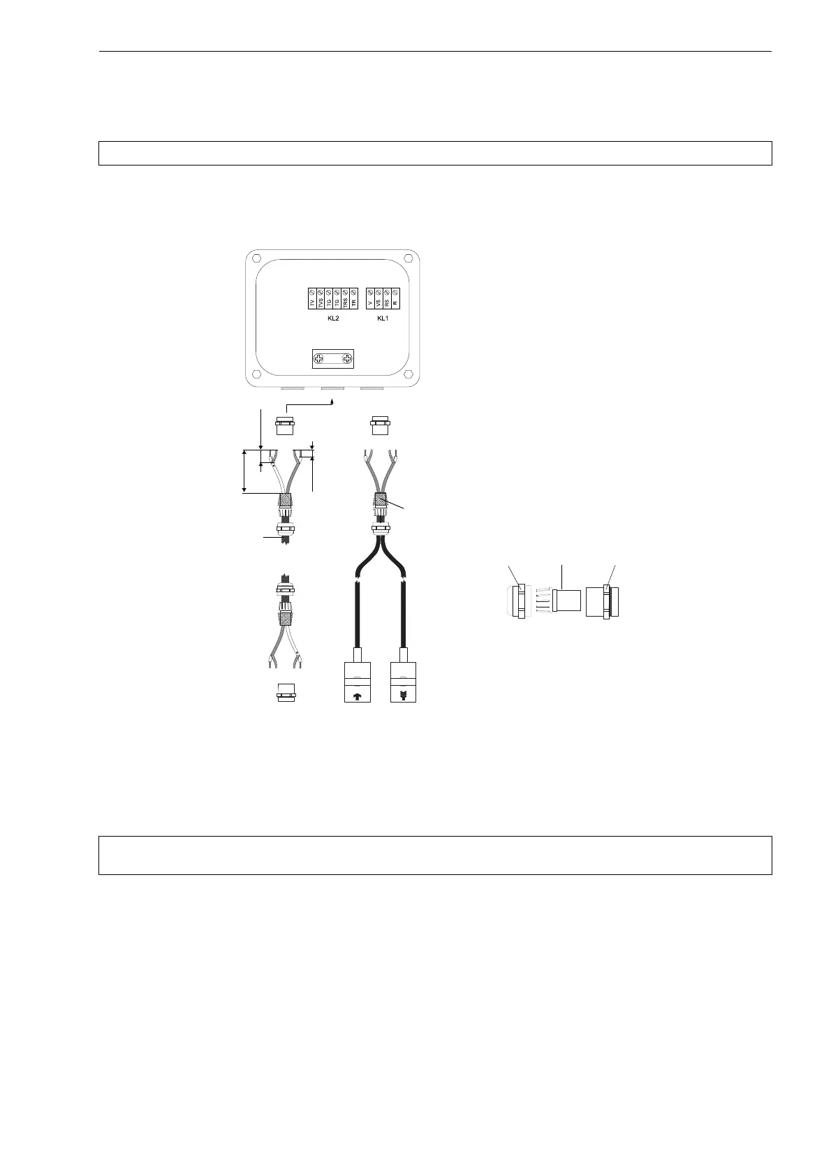
7.1.4 Connection of the Extension Cable to the Junction Box
• Remove the left blind plug for the connection of extension cable (see Fig. 7.23).
• Open the cable gland of the extension cable. The compression part remains in the cap nut.
• Push the extension cable through the cap nut and the compression part.
• Prepare the extension cable.
• Cut the external shield and brush it back over the compression part.
• Screw the gasket ring side of the basic part into the junction box.
• Insert the extension cable into the junction box.
• Fix the cable gland by screwing the cap nut onto the basic part.
• Connect the extension cable to the terminals of the transmitter (see Fig. 7.24 and Tab. 7.11).
Attention! Observe the "Safety Instructions for the Use in Explosive Atmosphere" (see document SIFLUXUS).
Fig. 7.23: Connection of the extension cable and the transducer cable
to the junction box JBxx (example with JB01)
Attention! For good high frequency shielding, it is important to ensure good electrical contact between the exter-
nal shield and the cap nut (and the junction box).
100 mm
20 mm
10 mm
cable gland
external shield,
brushed back
extension cable
cap nut
compression part basic part
 Loading...


