4 Description of the Transmitter FLUXUS F70x
UMFLUXUS_F7V4-6-2EN, 2017-10-01 19
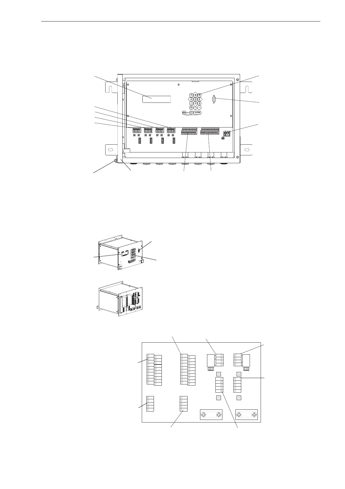
4.3 Design of FLUXUS F706
The front plate has to be removed to access the command panel.
4.4 Design of FLUXUS F709
The transmitter is designed as a 19 " module (42 HP, 3 U).
Fig. 4.3: Command panel of FLUXUS F706
Fig. 4.4: Command panel and terminal board of FLUXUS F709
T1a
T1b
S2 T2a
T3a T3b S4
T4aT2b
T4b
T1A T1B S1 T2A T3A T3B S3 T4AT2B T4B
A+ B- P1+ P2+ P4+ P5a P6a P7aP3+
101 103 P1- P2- P4- P5b P6b P7b
P8a P9a
P8b P9bP3-
PE
N(-)
L(+)
AVSAV
AGN
ARS
AR
BVSBV BGN BRS
BR
CVSCV CGN CRS
CR
DVSDV DGN DRS
DR
X_ARX_AV
KL3 KL2 KL1
ROM A
ROM B
ROM C
ROM D
X_BV X_BR X_CV X_CR X_DV X_DR
transducers
channel D
channel C
channel B
channel A
2x 16-digit LCD display,
backlit
serial interface RS232
outputs
power supply
inputs
keyboard
equipotential bonding
terminal
cover
K L 7
K L 5
K L 3
K L 1
X 7
K L 4K L 2
X 6 A V
X 8 B V
X 6 A R X 8 B R
X 5
BA
K L 6
K L 8
C H A N N E L
S A 3
S A 1
S A 2
S A 4
S B 3
S B 1
S B 2
S B 4
A V S
A V
A R S
A G N
A R
B V S
B V
B R S
B G N
B R
4 A +
4 B -
4 2
4 3
4 1
L +
L -
N
L 1
P E
P 6 a
P 7 a
P 7 +
P 5 a
P 6 +
P 2 +
P 5 +
P 1 +
P 3 +
P 4 +
P 6 b
P 7 b
P 7 -
P 5 b
P 6 -
P 2 -
P 5 -
P 1 -
P 3 -
P 4 -
T 4 A
T 4 B
T 3 B
S 3
T 3 A
T 1 B
T 2 B
T 1 A
S 1
T 2 A
T 4 a
T 4 b
T 3 b
S 4
T 3 a
T 1 b
T 2 b
T 1 a
S 2
T 2 a
2x 16-digit
LCD display,
backlit
serial interface
RS232
outputs
inputs
power
supply
transducers
measuring channel A
sensor module
measuring channel B
sensor module
measuring channel A
transducers
measuring channel B
serial interface
RS485
keyboard
 Loading...


