FLUXUS F808, F809 8 Installation of the Transducers
84 UMFLUXUS_F808_8091V1-2-1EN, 2019-08-23
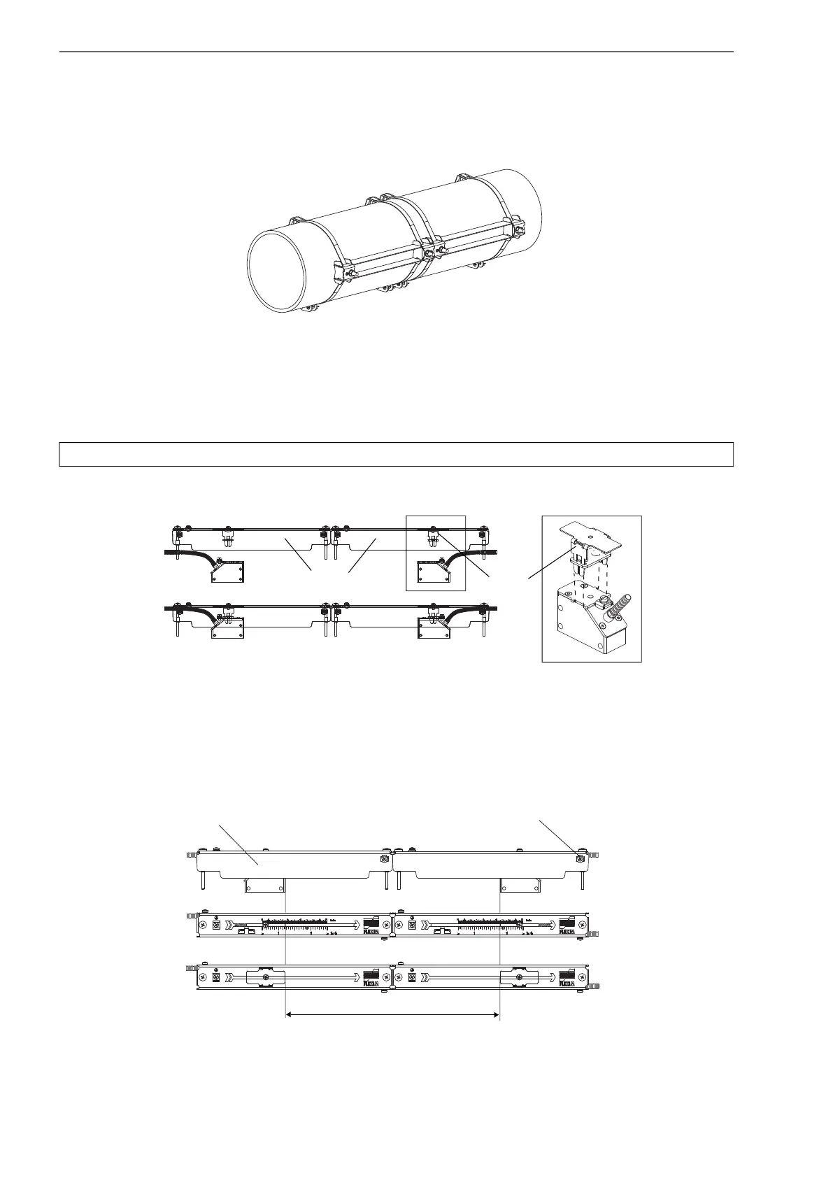
• Repeat the steps to fix the second rail (see Fig. 8.23).
8.3.5 Installation of the transducers in Variofix L
• Press the transducers firmly into the transducer clamping fixtures of the covers until the transducers are tightly fixed (one
transducer in each cover). The transducer cables show in opposite directions (see Fig. 8.24).
• Adjust the transducer distance displayed by the transmitter (see section 10.6 and Fig. 8.25).
• Fix the cables of the transducers with the strain relief clamp to protect them from mechanical strain (see Fig. 8.25).
• Put coupling foil (or some coupling compound for a short-term installation) on the contact surface of the transducers. The
coupling foil can be fixed to the contact surface with a small amount of coupling compound.
Fig. 8.23: Pipe with 2 rails
Note! The arrows on the transducers and the cover have to point in the same direction.
Fig. 8.24: Transducers in the covers
Fig. 8.25: Adjusting the transducer distance
cover
(1)
(2)
transducer
clamping
fixture
transducer distance
cover
strain relief clamp
 Loading...


