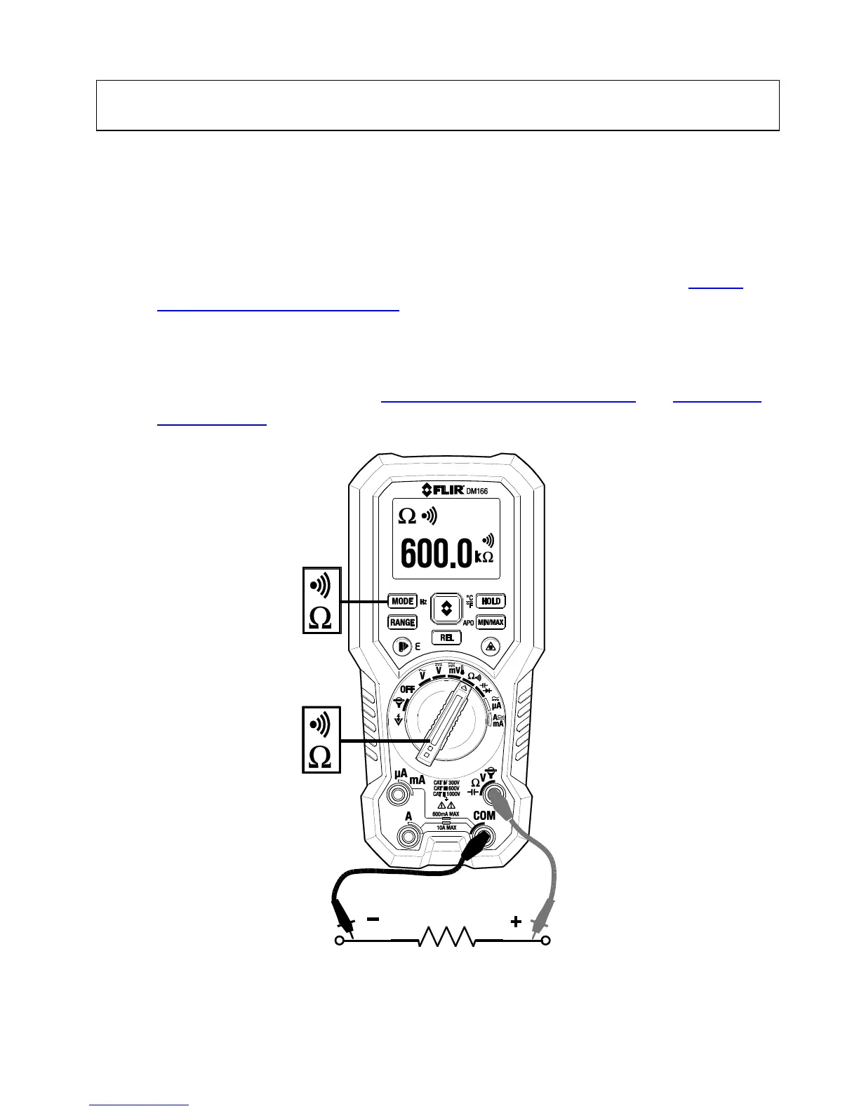
6.10 Resistance Measurements
Warning: Do not test resistance/continuity before removing power from capacitors
and other devices under test during a measurement. Injury to persons can occur.
1. Refer to Fig. 6-4. Set the function switch to the resistance position.
2. Short press MODE to step to the resistance mode.
3. Insert the black probe lead into the negative COM terminal and red probe lead
into positive Ω terminal.
4. Touch the tips of the probe across the circuit or component under test.
5. Read the resistance value on the display. The meter defaults to Auto Range
mode. To use Manual mode short press the RANGE button or refer to Section
6.1, Auto/Manual Range Modes.
6. If ‘OL’ appears, the signal is out of range. In this case, stop the test immediately
and review the application.
7. Short press the HOLD button to freeze/unfreeze the displayed reading.
8. For additional functions, see Section 6.5, MIN-MAX-AVG Mode and Section 6.6,
Relative Mode.
Fig. 6-4 Resistance and Continuity Measurements