7. IGM
TM
Thermal Imager Operation
7.1 IGM
TM
(Infrared Guided Measurements) Basics
In the Thermal Imaging mode, the user can measure a targeted surface’s temperature.
The DM166 accomplishes this by detecting the energy emitted by the surface under
test. The DM166 ‘sees’ a thermal image of an area under test in the same manner as
with a dedicated thermal imaging device. See Section 7.4, Infrared Energy and Thermal
Imaging Overview for in-depth information. The DM166 laser pointer and cross hairs
assist in targeting.
Press the IGM button to open the Thermal Imager. In Fig 7-1, the meter is set to color
palette IRON. Short press the Palette/Emissivity button to select other colors.
Long press the Emissivity button to open the emissivity-setting menu. Press the
Emissivity button to scroll to the desired setting, press and hold the emissivity button
to exit. See Section 7.3, Emissivity Factors for Common Materials
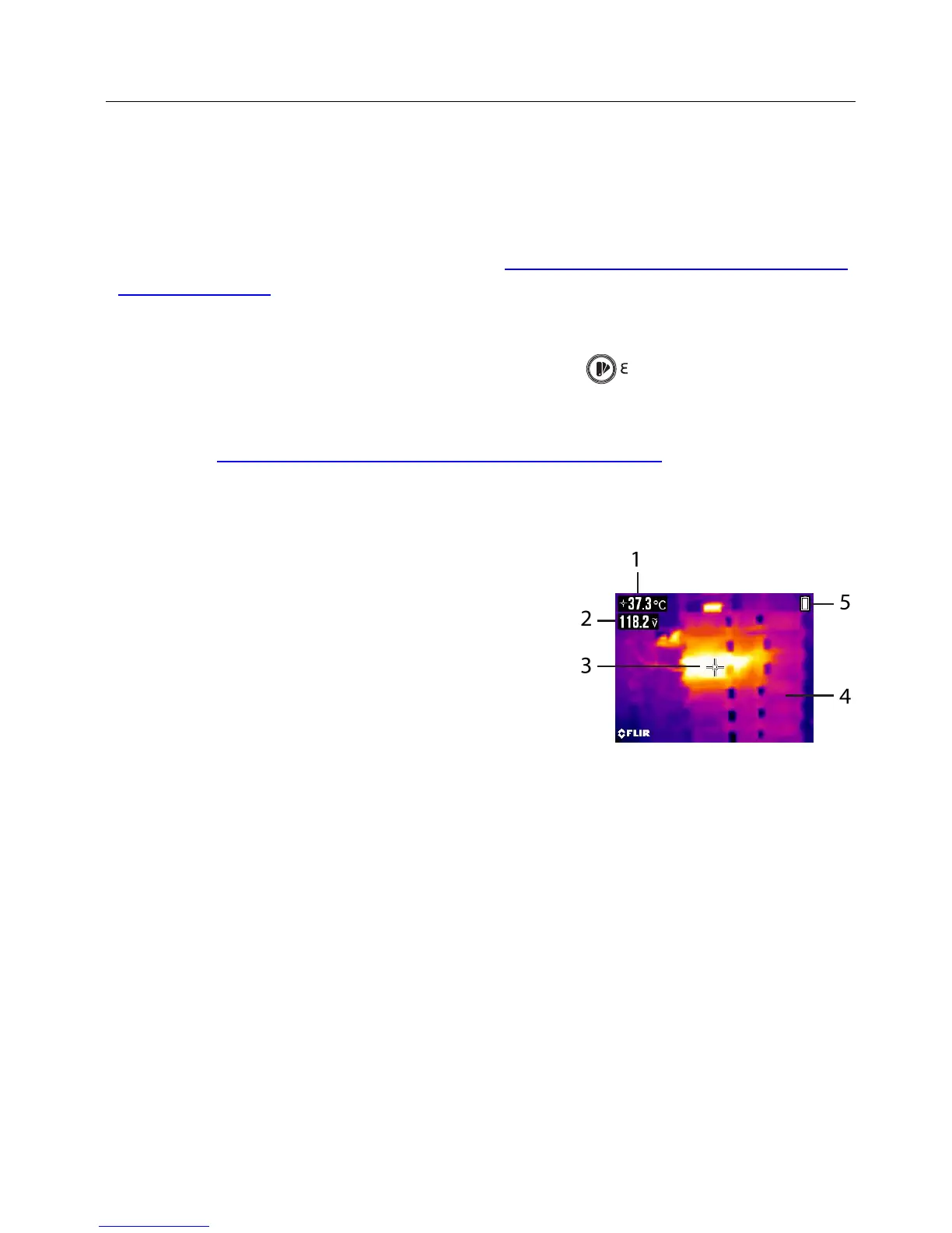
7.1.1 Thermal Image Display Description (refer to Fig. 7-1 for the list below)
1. Surface temperature measurement represents
the temperature of the spot. Dashes display
while the temperature reading stabilizes
2. DMM measurement data
3. Cross hairs for spot targeting
4. Thermal image frame
5. Icon area
Fig. 7-1 IGM Display Example
7.1.2 Thermal Imager Operation
1. Set the function switch to any position.
2. Short press the IGM button to switch the Thermal Imager ON. Short press again to
clear image of all text and icons. Short press again to exit the imager mode.
3. With the Imager on, point the lens (back of meter) at the target.
4. The display will show the temperature measurement in the upper left hand corner
for the targeted area.
5. Use the laser pointer and cross hairs for targeting. Press and hold the laser button
to use the pointer; release the button to switch OFF the laser.
6. In the Thermal imaging mode, the meter continues to operate normally as a
Multimeter; the electrical symbols appear on the left side of the display.