4. Meter Description and Reference Guide
4.1 Front and Back Meter Descriptions
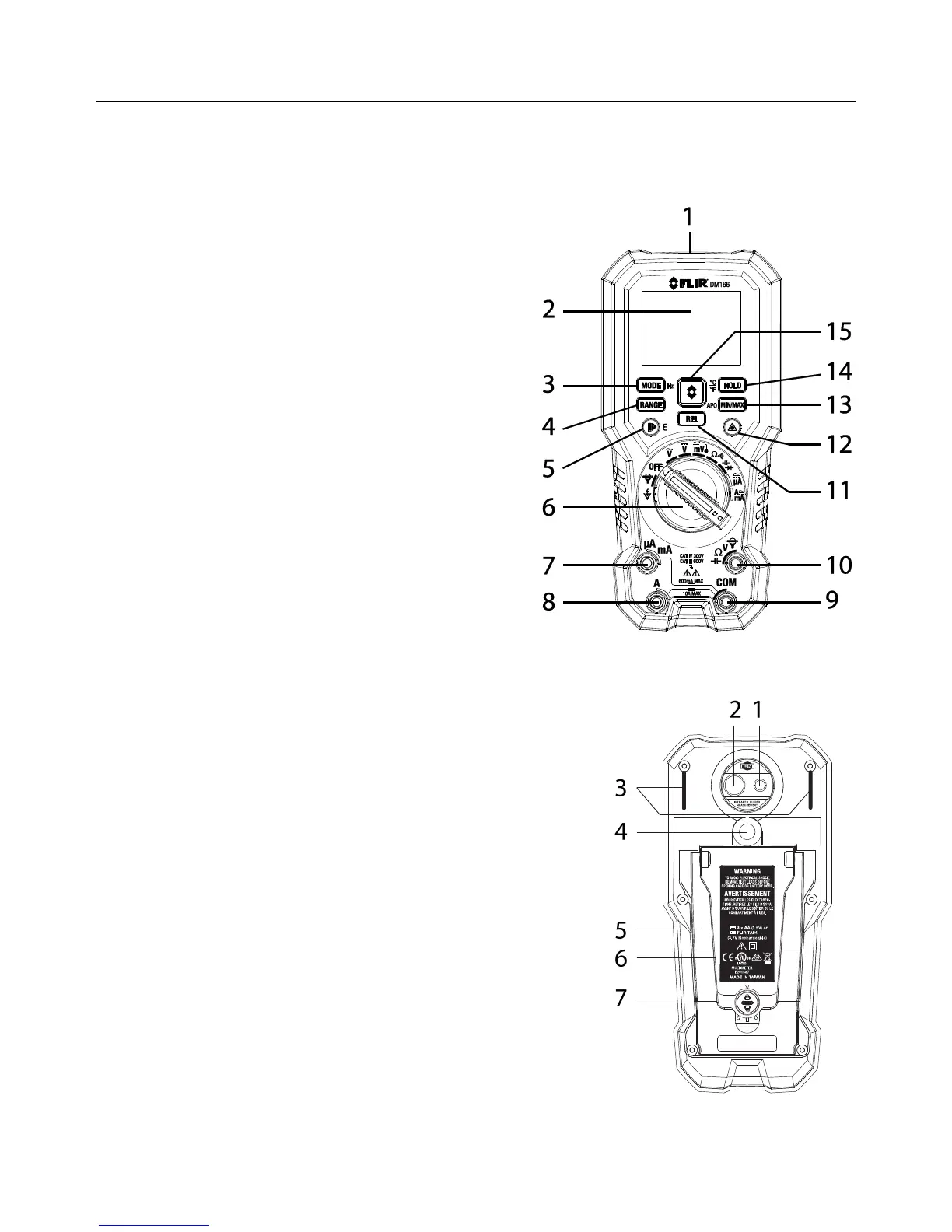
Fig. 4-1 Front View
1. NCV sensor
2. LCD display
3. MODE/Hz button
4. RANGE button
5. Palette/Emissivity button
6. Function Switch
7. Positive (+) Probe Input Jack for µA/mA
(Current)
8. Positive (+) Probe Input Jack for Amps
(Current)
9. COM (-) Probe Input Jack
10. Positive (+) Probe Input Jack for all inputs
except Amps, mA, and µA
11. Relative (REL) button
12. Laser pointer ON/OFF button
13. MIN-MAX/APO button
14. HOLD/Temperature units button
15. Thermal Image mode button
1. Laser lens
2. Thermal imaging lens
3. Test Lead holder mounts
4. Tripod mount
5. Tilt stand
6. Battery/Fuse compartment
7. Battery/Fuse door lock
Fig. 4-2 Rear View