432-0003-00-12 Rev 140 — M-Series Installation Guide 9
Installing M-Series Systems
Camera Video Options
The M-Series gimbal assembly has either one or two video cables:
• The cable labeled IR is for the composite—also known as analog—video
signal from the thermal (infrared) camera. This is the only cable on single
payload cameras.
• On dual payload models, the cable labeled VIS/IR is for video from either the
thermal camera or the DLTV camera. You use the JCU to determine which
output displays.
The video from dual payload models can be output on one or two video displays.
If only a single display with a single video input is available, connect the cable
labeled VIS/IR to the display. If the display has more than one video input, both
video cables can be connected to the same display. In this type of installation,
switching between the thermal and visible video channels is performed with the
display controls, rather than the JCU.
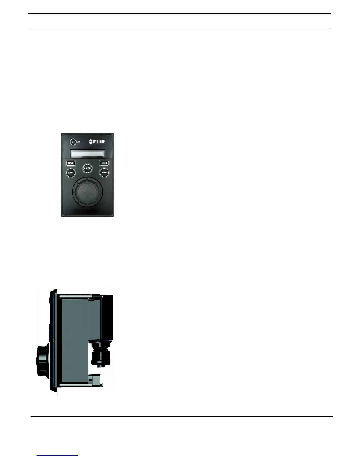
Joystick Control Unit (JCU)
Mount the JCU in a convenient area that is close to the monitor being used to
display the M-Series video output. Make sure the area you choose leaves enough
room for the cable under the JCU (refer to the M-Series ICD for dimensions). The
magnetic compass safe distance for the JCU is 55 cm (21.7 in).
The JCU can be mounted to the dash (or other surface) in any orientation, using
four captive mounting screws that hold panel mounting clamps. When the
mounting screws are tightened, the panel mounting clamps rotate and extend
away from the JCU at a right angle, and come into contact with the mounting
surface. The JCU can be mounted to dash thicknesses ranging from 0.16 – 4.45
cm (0.063 – 1.750 in). A trim bezel snaps on top of the JCU to cover the mounting
screws. See “Installing the Joystick Control Unit (JCU)” on page 12 for detailed
instructions.
JCU Connection to Camera
The JCU is a Power over Ethernet (PoE) device and can be connected to the
camera directly with the included 7.6 meter (25 feet) double-shielded Ethernet
cable or a user-supplied cable of sufficient length. In this case, the JCU draws its
power from the camera.
Alternatively, the camera and the JCU can be connected together via an Ethernet
switch; this type of configuration allows more than one JCU or camera to be used.
The JCU draws its power through the Ethernet connection, so a PoE injector or
PoE switch is required.
Prior to Cutting/Drilling Holes
Determine if any interior trim panels must be removed in order to gain access to
the mounting hardware, and remove them ahead of time.
 Loading...