432-0003-00-12 Rev 140 — M-Series Installation Guide 7
Installing M-Series Systems
Contact FLIR (phone numbers listed on the back cover of this manual) for more
information regarding available accessories including JCUs, PoE equipment,
video distribution amplifiers, cables, connectors, and mounting hardware.
Installation Planning
You should consider a number of factors in planning the installation of the
M-Series camera and JCU.
General Location Considerations
First determine a good location for mounting the M-Series camera unit and the
JCU. The camera requires at least three connections:
• One for power
• One network connection to the JCU or a PC
• One or two for the video display or displays
Optionally, more than one JCU can be used to control the camera and more than
one display can be used to view the video. Also a single JCU can be used to
control more than one camera. Most often, the JCU and the video monitor are
mounted close together, as a pair, so the video can be viewed when the camera
position (pan or tilt) is changed with the JCU.
When determining the component locations, consider how the system may be
expanded in the future. For example, you may want to add an additional monitor,
or perhaps a JCU and monitor pair.
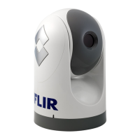
Camera Location Considerations
Consider the following points when determining the camera location:
• Mount the IP66-rated M-Series camera body as high as practical, but without
interfering with any radar, navigational, or communications electronics. and
minimizing the degree to which vessel structures block the camera’s 360°
view. The camera’s continuous-pan design lets it rotate and point in all
directions. It is good practice to test the unit at the planned installation location
with typical vessel electronics active prior to mounting the camera.
• Mount the camera as close to the vessel’s center line as possible so you will
have a symmetrical view of on-coming traffic, obstacles, and other navigational
hazards.
• An appropriate camera mount suited for the camera mass and potential
vibration and mechanical shock is important for proper camera functioning.
The camera is tested to hold position for mechanical shock up to 9g transverse
and 15g vertical. Improper mounts that are loose and/or resonate can magnify

 Loading...