432-0003-00-12 Rev 140 — M-Series Installation Guide 13
Installing M-Series Systems
Caution: An installation template is provided in the JCU ICD. If you print the
template from the PDF file, ensure that it was printed to the correct scale by
checking the dimensions prior to cutting any holes.
Standard JCU Mounting Instructions
1. Using the JCU template supplied as a guide in Doc. # 500-0385-19, mark the
location of the rectangular opening that will allow the JCU to be recessed in the
vessel’s control console. Ensure the corners are marked precisely and cut
square.
2. Apply the adhesive side of the rubber gasket to the back of the JCU on the
surface that faces the mounting platform. The JCU comes with 4 panel
mounting clamps that can be reversed when the thickness of the panel
material is less than 0.79 cm (5/16 or 0.31 in); see instructions below. Ensure
the mounting clamps are rotated inward and are recessed so the entire JCU
fits into the hole
3. Remove boots from both ends of the Ethernet cable, as it may interfere with
the coupling gland. The boot may cause the RJ45 connector tab to depress,
which can lead to intermittent connections.
4. Loosen or remove the cable gland nut on the JCU, and insert the Ethernet
cable RJ45 connector through the gland nut. Once the Ethernet cable is
connected to the JCU, replace the gland nut and turn the nut 1/4 turn beyond
hand tight.
5. Insert the JCU into the hole and secure by turning the 4 corner screws
clockwise. Rotate each screw one full turn and ensure the mounting clamps
are rotated outward from the JCU housing. Tighten the screws to draw the
mounting clamps up against the mounting surface and then tighten another
quarter or half turn. Do not overtighten the screws.
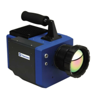
Mounting the JCU to a Thin Panel
As shipped from the factory, the JCU can be mounted to dash thicknesses
ranging from 0.79 – 4.45 cm (0.31 – 1.75 in). The clamps are set with the small
foot on the clamp facing away from the panel and toward the front of the JCU, as
shown below.
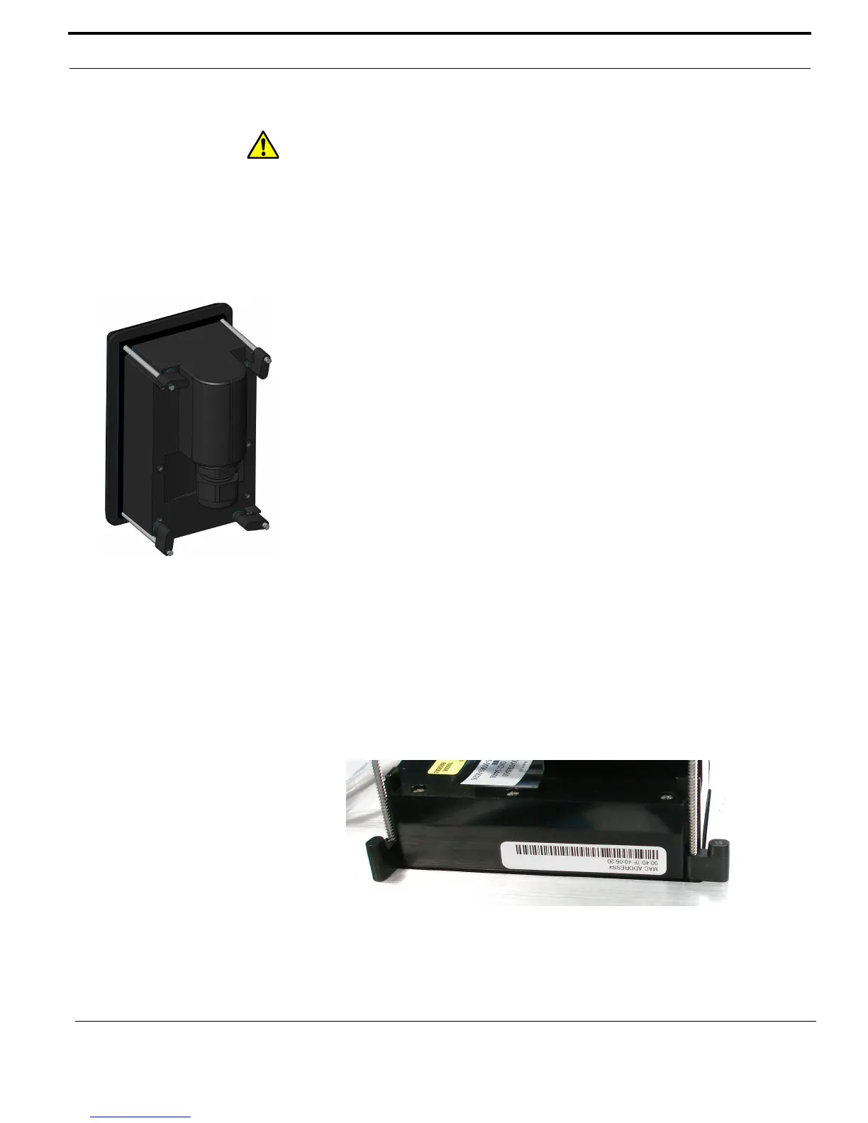
If you intend to mount the JCU to a panel of 0.79 cm (0.31 in) thickness or less,
remove the clamps from the mounting screws, turn them around and thread them
back onto each of the four screws. In this configuration, the clamp foot faces the

 Loading...