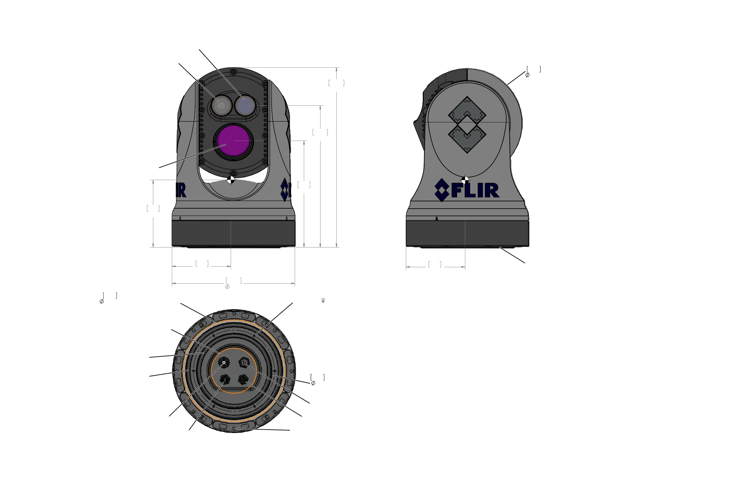
9.61
244.2
AS568A-436 EPDM O-Ring
[5.85in ID x .275in DIA]
149mm ID x 7mm DIA
AS658A-444 EPDM O-Ring
[7.72in ID x .275in DIA]
196mm ID x 7mm DIA
7.09
180.0
bolt circle
8.86
225.0
min base plate diameter
for effective o-ring seal
Cable port dimensions depend on
Mounting solution and cable type.
Warranty void if screws removed
HD/SDI BNC connector
Ethernet connector
Power connector
Analog video and serial connector
6X M6X1.0
10
O-Ring used for sealing system to mounting structure.
Stand alone unit meets IPx6 sealing specification.
Minimum
mounting surface flatness of 1.5mm [0.060in]
over system diameter required for o-ring use. When
mounting to irregular surfaces, use of bedding compound
is recommended.
Use Loctite 262 with all metal to metal threaded connections
that do not have locking patches.
Warning
Do not bottom fasteners in base.
Bolt length not to exceed 6mm into base.
Electronics will be damaged by base penetration - voiding warranty.
Bolt torque not to exceed 4.5 N-m (3.3 lb-ft).
Clearance required for free motion of system. Clearance required for free motion of system.

 Loading...